Table of Contents
Proper Procedure for Calibrating Rosemount Flow Transmitter
Calibrating a Rosemount flow transmitter is a crucial step in ensuring accurate and reliable measurements of flow rates in industrial processes. Proper calibration not only improves the performance of the transmitter but also helps in maintaining the overall efficiency of the system. In this article, we will discuss the step-by-step procedure for calibrating a Rosemount flow transmitter.
Before starting the calibration process, it is important to gather all the necessary tools and equipment. You will need a calibration kit, a pressure source, a multimeter, and a laptop or computer with the necessary software for communicating with the transmitter. Make sure that the transmitter is properly installed and connected to the process piping before proceeding with the calibration.
The first step in calibrating a Rosemount flow transmitter is to establish a baseline measurement. This involves verifying the zero and span settings of the transmitter to ensure that it is operating within the specified range. To do this, apply zero pressure to the transmitter and adjust the zero trim potentiometer until the output signal reads zero. Next, apply a known pressure to the transmitter and adjust the span trim potentiometer until the output signal matches the expected value.
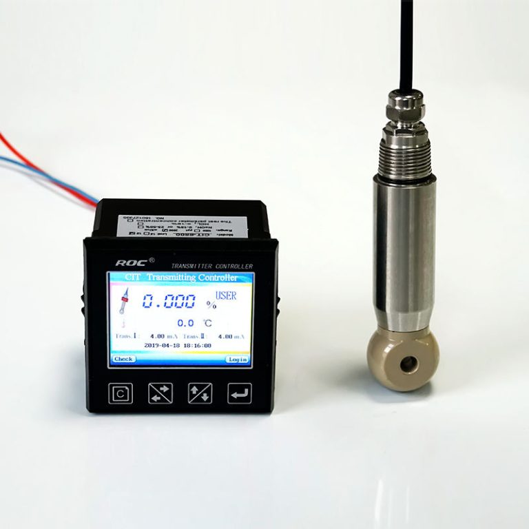
| Model No. | CIT-8800 Inductive Conductivity / Concentration Online Controller | |
| Measurement range | Conductivity | 0.00μS/cm ~ 2000mS/cm |
| Concentration | 1.NaOH,(0-15)% or(25-50)%; | |
| 2.HNO3(note the Corrosion resistance of the sensor)(0-25)% or(36-82)%; | ||
| 3.User-defined concentration curves. | ||
| TDS | 0.00ppm~1000ppt | |
| Temp. | (0.0 ~ 120.0)℃ | |
| Resolution | Conductivity | 0.01μS/cm |
| Concentration | 0.01% | |
| TDS | 0.01ppm | |
| Temp. | 0.1℃ | |
| Accuracy | Conductivity | 0μS/cm ~1000μS/cm ±10μS/cm |
| 1 mS/cm~500 mS/cm ±1.0% | ||
| 500mS/cm~2000 mS/cm ±1.0% | ||
| TDS | 1.5 level | |
| Temp. | ±0.5℃ | |
| Temp. compensation | element | Pt1000 |
| range | (0.0~120.0)℃ linear compensation | |
| (4~20)mA Current output | channels | Double channels |
| features | Isolated, adjustable, reversible, 4-20MA output, instruments/ transmitter mode. | |
| Loop resistance | 400Ω(Max),DC 24V | |
| Resolution | ±0.1mA | |
| Control contact | Channels | Triple channels |
| Contact | Photoelectric relay output | |
| Programmable | Programmable ( temperature 、conductivity/concentration/TDS、timing)output | |
| Features | Could set temperature、conductivity/concentration/TDS、 timing NO/NC/ PID selection | |
| Resistance load | 50mA(Max),AC/DC 30V(Max) | |
| Data communication | RS485,MODBUS protocol | |
| Power supply | DC 24V±4V | |
| Consumption | <5.5W | |
| Working environment | Temperature:(0~50)℃ Relative Humidity:≤85%RH(non- condensing ) | |
| Storage | Temperature:(-20~60)℃ Relative Humidity:≤85%RH(non- condensing) | |
| Protection level | IP65(with rear cover) | |
| Outline dimension | 96mm×96 mm×94mm (H×W×D) | |
| Hole dimension | 91mm×91mm(H×W) | |
| Installation | Panel mounted , fast installation | |
Once the baseline measurement has been established, the next step is to perform a calibration check. This involves comparing the output signal of the transmitter against a known reference standard to verify its accuracy. Connect the transmitter to the calibration kit and apply a series of pressure values to the transmitter. Record the output signal at each pressure point and compare it to the expected values. If there are any discrepancies, adjust the zero and span settings accordingly.
After completing the calibration check, it is important to perform a linearity test to ensure that the transmitter is providing accurate measurements across the entire range. Apply a series of pressure values to the transmitter and record the output signal at each point. Plot the data on a graph and check for any deviations from a straight line. If the data points deviate significantly from the expected line, adjustments may be necessary to improve the linearity of the transmitter.
Once the linearity test has been completed, the final step is to document the calibration results. Record the baseline measurement, calibration check results, and linearity test data in a calibration report. Include details such as the date of calibration, the technician’s name, and any adjustments made to the transmitter settings. This documentation is important for maintaining a record of the calibration history and ensuring compliance with regulatory requirements.

In conclusion, calibrating a Rosemount flow transmitter is a critical task that should be performed regularly to ensure accurate and reliable measurements. By following the proper procedure outlined in this article, you can maintain the performance of your transmitter and improve the overall efficiency of your industrial processes. Remember to gather all the necessary tools and equipment, establish a baseline measurement, perform a calibration check, conduct a linearity test, and document the calibration results. With proper calibration, you can trust that your Rosemount flow transmitter will provide accurate and consistent flow rate measurements.
Common Mistakes to Avoid When Calibrating Rosemount Flow Transmitter
Calibrating a Rosemount flow transmitter is a crucial step in ensuring accurate and reliable flow measurements in industrial processes. However, there are common mistakes that can occur during the calibration process that can lead to inaccurate readings and potential issues down the line. In this article, we will discuss some of these common mistakes and provide tips on how to avoid them.
One common mistake when calibrating a Rosemount flow transmitter is not following the manufacturer’s guidelines. It is important to carefully read and understand the calibration procedures outlined in the user manual provided by Rosemount. Failure to follow these guidelines can result in improper calibration and inaccurate flow measurements. Make sure to familiarize yourself with the specific requirements for your particular model of Rosemount flow transmitter before beginning the calibration process.
| FCT-8350 Flow Transmitter | |
| Measurement range | Instantaneous flow:(0~2000)m3/h;Accumulated flow:(0~99999999)m3 |
| Flow rate | (0~5)m/s |
| Applicable pipe diameter | DN 25~DN 1000 for selection |
| Resolution | 0.001 m3/h |
| Renew interval | 1S |
| Accuracy | 2.0 level |
| Repeatability | ±0.5% |
| Probe input | Range :0.5Hz~2KHz;Power supply:DC 12V(instrument supply) |
| Analog output | (4~20)mA,Instrument/transmitter for selection; |
| Control output | Semi-conductor photo electronic relay,Load current 50mA(max),AC/DC 30V |
| Control mode | Instantaneous flow high/low limit alarm, flow variable frequency conversion |
| Working power | DC24V |
| Power consumption: | <3.0W |
| Cable length | 5m as standard ; or(1~500)m for selection |
| Working environment | Temp.:(0~50)℃;relative humidity≤85%RH(non condensation) |
| Storage environment | Temp.:(-20~60)℃; relative humidity:≤85%RH(non condensation) |
| Protection level | IP65(with back cover) |
| Dimension | 96 mm×96 mm×94mm (H×W×D) |
| Hole size | 91mm×91mm(H×W) |
| Installation | Panel mounted,fast installation |
Another common mistake is not properly preparing the equipment before calibration. Before calibrating the flow transmitter, it is important to ensure that the equipment is clean and free of any debris or obstructions that could affect the calibration process. Additionally, make sure that all necessary tools and equipment are readily available and in good working condition. Taking the time to properly prepare the equipment before calibration can help ensure accurate and reliable results.
One of the most common mistakes made during calibration is not allowing enough time for the process. Calibrating a flow transmitter can be a time-consuming task, and rushing through the process can lead to errors and inaccuracies. It is important to set aside an adequate amount of time for calibration and to follow each step carefully to ensure accurate results. Taking the time to properly calibrate the flow transmitter will help prevent issues and ensure reliable flow measurements.
Another common mistake to avoid when calibrating a Rosemount flow transmitter is not performing regular calibrations. Over time, the performance of the flow transmitter can drift, leading to inaccurate readings. It is important to establish a regular calibration schedule and adhere to it to ensure that the flow transmitter is operating correctly. Regular calibrations can help identify any issues early on and prevent potential problems in the future.
One final common mistake to avoid when calibrating a Rosemount flow transmitter is not documenting the calibration process. Keeping detailed records of each calibration, including the date, time, and results, can help track the performance of the flow transmitter over time. This documentation can be valuable for troubleshooting any issues that may arise and for ensuring compliance with regulatory requirements.
In conclusion, calibrating a Rosemount flow transmitter is a critical task that should be done carefully and accurately to ensure reliable flow measurements. By avoiding common mistakes such as not following manufacturer guidelines, not properly preparing equipment, rushing through the process, neglecting regular calibrations, and failing to document the process, you can help ensure accurate and reliable results. Taking the time to calibrate your Rosemount flow transmitter correctly will help prevent issues and ensure accurate flow measurements in your industrial processes.