Understanding the Features of the Burkert conductivity meter 8228 Manual
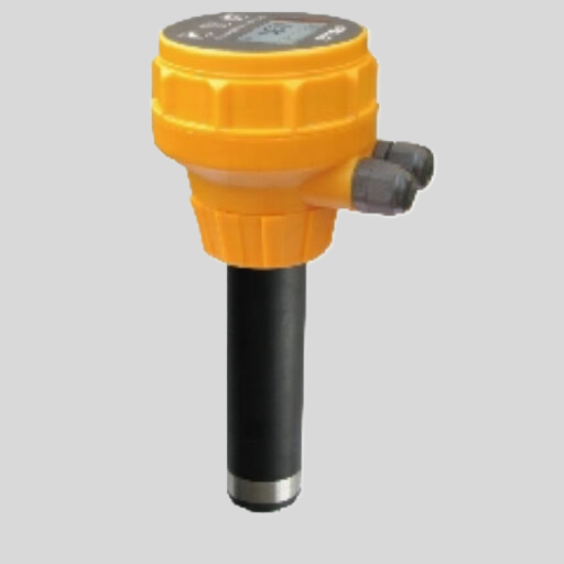
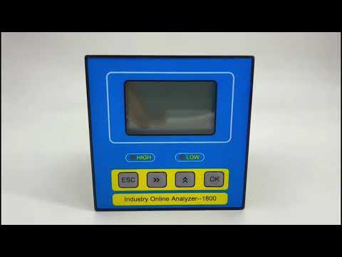
The Burkert conductivity meter 8228 is a versatile and reliable instrument used for measuring the conductivity of liquids in various industrial applications. To fully utilize the capabilities of this device, it is essential to understand the features outlined in the manual provided by the manufacturer.
One of the key features of the Burkert conductivity meter 8228 manual is the detailed instructions on how to calibrate the device. Calibration is crucial for ensuring accurate and reliable measurements. The manual provides step-by-step guidance on how to perform calibration procedures, including the use of calibration standards and adjustment of calibration factors. By following the instructions in the manual, users can ensure that their conductivity meter is operating at peak performance.
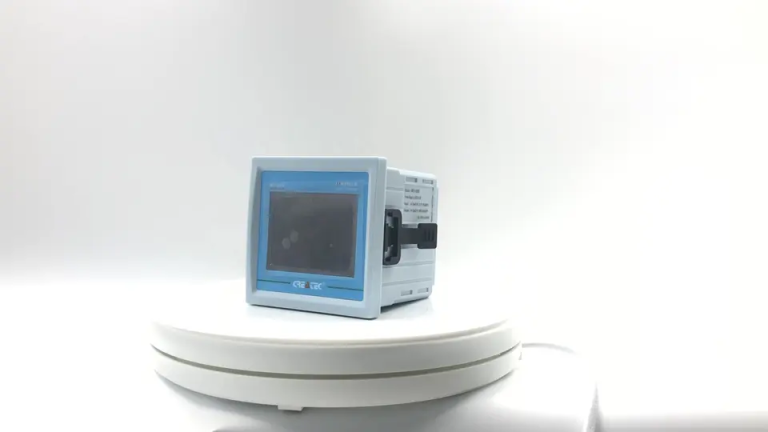
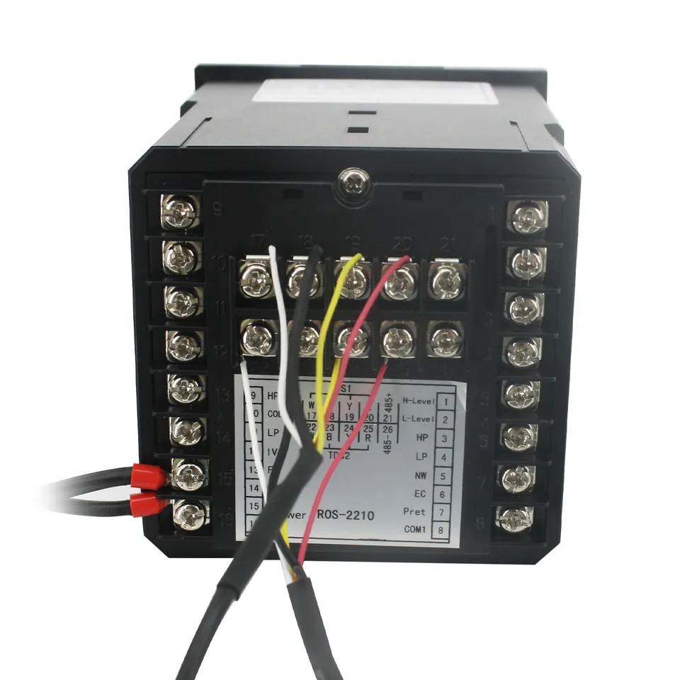
| Model | CM-230S Ecomonical conductivity monitor |
| Range | 0-200/2000/4000/10000uS/cm |
| 0-100/1000/2000/5000PPM | |
| Accuracy | 1.5%(FS) |
| Temp. Comp. | Automatic temperature compensation based on 25℃ |
| Oper. Temp. | Normal 0~50℃; High temp 0~120℃ |
| Sensor | Standard:ABS C=1.0cm-1 (others are optional) |
| Display | LCD Screen |
| Zero Correction | Manual correction for low range 0.05-10ppm Set from ECO |
| Unit Display | uS/cm or PPM |
| Power | AC 220V±10% 50/60Hz or AC 110V±10% 50/60Hz or DC24V/0.5A |
| Working Environment | Ambient temperature:0~50℃ |
| Relative humidity≤85% | |
| Dimensions | 48×96×100mm(H×W×L) |
| Hole Size | 45×92mm(H×W) |
| Installation Mode | Embedded |
In addition to calibration, the manual also provides information on the various measurement modes and settings available on the Burkert conductivity meter 8228. Users can choose between different measurement ranges, temperature compensation options, and electrode configurations to suit their specific application requirements. The manual explains how to navigate the menu system and select the appropriate settings for optimal performance.
Another important feature of the Burkert conductivity meter 8228 manual is the troubleshooting section. This section provides guidance on common issues that users may encounter while using the device, such as sensor drift, temperature fluctuations, or electrical interference. By following the troubleshooting steps outlined in the manual, users can quickly identify and resolve any problems that may arise, minimizing downtime and ensuring accurate measurements.
The manual also includes information on maintenance and care of the Burkert conductivity meter 8228. Proper maintenance is essential for prolonging the life of the device and ensuring consistent performance. The manual provides guidance on how to clean and store the device, as well as how to replace consumable parts such as electrodes and O-rings. By following the maintenance instructions in the manual, users can keep their conductivity meter in top condition for years to come.
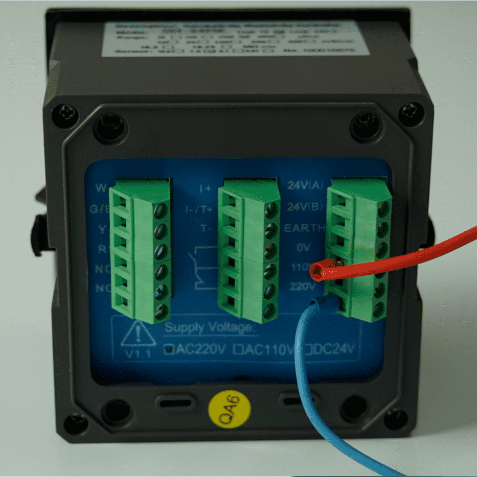
| ROS-360 Water Treatment RO Programmer Controller | ||
| Model | ROS-360 Single Stage | ROS-360 Double Stage |
| Measuring range | Source water0~2000uS/cm | Source water0~2000uS/cm |
| First level effluent 0~1000uS/cm | First level effluent 0~1000uS/cm | |
| secondary effluent 0~100uS/cm | secondary effluent 0~100uS/cm | |
| Pressure sensor(optional) | Membrane pre/post pressure | Primary/ secondary membrane front/rear pressure |
| Flow Sensor(optional) | 2 channels (Inlet/outlet flow rate) | 3 channels (source water, primary flow,secondary flow) |
| IO input | 1.Raw water low pressure | 1.Raw water low pressure |
| 2.Primary booster pump inlet low pressure | 2.Primary booster pump inlet low pressure | |
| 3.Primary booster pump outlet high pressure | 3.Primary booster pump outlet high pressure | |
| 4.High liquid level of Level 1 tank | 4.High liquid level of Level 1 tank | |
| 5.Low liquid level of Level 1 tank | 5.Low liquid level of Level 1 tank | |
| 6.Preprocessing signal | 6.2nd booster pump outlet high pressure | |
| 7.High liquid level of Level 2 tank | ||
| 8.Preprocessing signal | ||
| Relay output (passive) | 1.Water inlet valve | 1.Water inlet valve |
| 2.Source water pump | 2.Source water pump | |
| 3.Booster pump | 3.Primary booster pump | |
| 4.Flush valve | 4.Primary flush valve | |
| 5.Water over standard discharge valve | 5.Primary water over standard discharge valve | |
| 6.Alarm output node | 6.Secondary booster pump | |
| 7.Manual standby pump | 7.Secondary flush valve | |
| 8.Secondary water over standard discharge valve | ||
| 9.Alarm output node | ||
| 10.Manual standby pump | ||
| The main function | 1.Correction of electrode constant | 1.Correction of electrode constant |
| 2.TDS alarm setting | 2.TDS alarm setting | |
| 3.All working mode time can be set | 3.All working mode time can be set | |
| 4.High and low pressure flushing mode setting | 4.High and low pressure flushing mode setting | |
| 5.Manual/automatic can be chosen when boot up | 5.Manual/automatic can be chosen when boot up | |
| 6.Manual debugging mode | 6.Manual debugging mode | |
| 7.Spare parts time management | 7.Spare parts time management | |
| Expansion interface | 1.Reserved relay output | 1.Reserved relay output |
| 2.RS485 communication | 2.RS485 communication | |
| Power supply | DC24V±10% | DC24V±10% |
| Relative humidity | ≦85% | ≤85% |
| Environment temperature | 0~50℃ | 0~50℃ |
| Touch screen size | Touch screen size: 7 inches 203*149*48mm (Hx Wx D) | Touch screen size: 7 inches 203*149*48mm (Hx Wx D) |
| Hole Size | 190x136mm(HxW) | 190x136mm(HxW) |
| Installation | Embedded | Embedded |
Overall, the Burkert conductivity meter 8228 manual is a valuable resource for users looking to maximize the performance of their device. By understanding the features outlined in the manual, users can calibrate their device accurately, select the appropriate measurement settings, troubleshoot any issues that may arise, and maintain their device for long-term reliability. With the information provided in the manual, users can confidently use their Burkert conductivity meter 8228 to achieve accurate and consistent conductivity measurements in their industrial applications.

