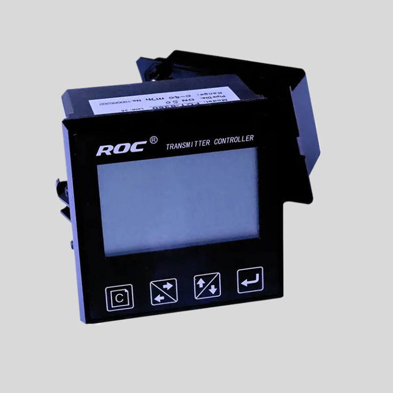
Exploring the Components of a conductivity meter Diagram
A conductivity meter diagram is a visual representation of the components that make up a conductivity meter, a device used to measure the ability of a solution to conduct electricity. Understanding the various parts of a conductivity meter diagram is essential for anyone working in a laboratory setting or conducting experiments that require accurate measurements of conductivity.
| FCT-8350 Flow Transmitter | |
| Measurement range | Instantaneous flow:(0~2000)m3/h;Accumulated flow:(0~99999999)m3 |
| Flow rate | (0~5)m/s |
| Applicable pipe diameter | DN 25~DN 1000 for selection |
| Resolution | 0.001 m3/h |
| Renew interval | 1S |
| Accuracy | 2.0 level |
| Repeatability | \u00b10.5% |
| Probe input | Range :0.5Hz~2KHz;Power supply:DC 12V(instrument supply) |
| Analog output | (4~20)mA,Instrument/transmitter for selection; |
| Control output | Semi-conductor photo electronic relay,Load current 50mA(max),AC/DC 30V |
| Control mode | Instantaneous flow high/low limit alarm, flow variable frequency conversion |
| Working power | DC24V |
| Power consumption: | <3.0W |
| Cable length | 5m as standard ; or(1~500)m for selection |
| Working environment | Temp.:(0~50)\u2103;relative humidity\u226485%RH(non condensation) |
| Storage environment | Temp.:(-20~60)\u2103; relative humidity:\u226485%RH(non condensation) |
| Protection level | IP65(with back cover) |
| Dimension | 96 mm\u00d796 mm\u00d794mm (H\u00d7W\u00d7D) |
| Hole size | 91mm\u00d791mm(H\u00d7W) |
| Installation | Panel mounted,fast installation |
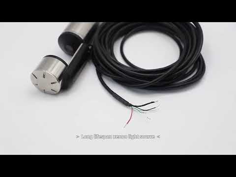
One of the key components of a conductivity meter diagram is the probe, which is the part of the meter that comes into contact with the solution being tested. The probe is typically made of a material that is a good conductor of electricity, such as stainless steel or graphite. It is important that the probe is clean and free of any contaminants that could affect the accuracy of the conductivity measurement.
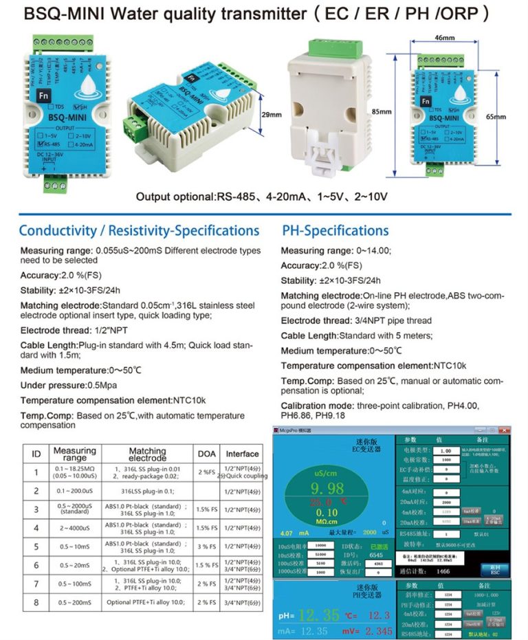
Connected to the probe is the sensor, which is responsible for detecting the electrical conductivity of the solution. The sensor converts the electrical conductivity of the solution into a signal that can be read by the meter. The sensor is a crucial component of the conductivity meter diagram, as it is responsible for providing accurate measurements of conductivity.
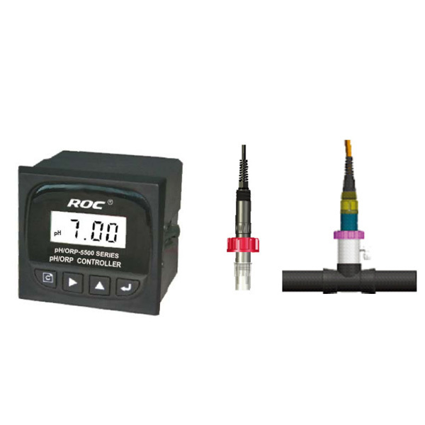
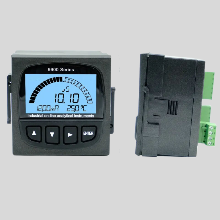
The meter itself is another important component of the conductivity meter diagram. The meter is the part of the device that displays the conductivity measurement in units such as microsiemens per centimeter (\u00b5S/cm) or millisiemens per centimeter (mS/cm). The meter may also have additional features such as a digital display or the ability to store and recall measurements.
In addition to the probe, sensor, and meter, a conductivity meter diagram may also include other components such as a temperature sensor. Temperature can have a significant impact on the conductivity of a solution, so many conductivity meters are equipped with a temperature sensor to compensate for changes in temperature. This ensures that the conductivity measurement is accurate regardless of variations in temperature.
Another important component of a conductivity meter diagram is the calibration controls. Calibration is essential for ensuring the accuracy of conductivity measurements, and most conductivity meters have built-in calibration controls that allow the user to calibrate the meter as needed. Calibration controls may include buttons or dials that allow the user to adjust the meter to a known standard solution.
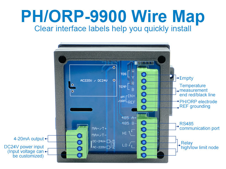
Overall, a conductivity meter diagram provides a comprehensive overview of the components that make up a conductivity meter and how they work together to measure the conductivity of a solution. By understanding the various parts of a conductivity meter diagram, users can ensure that their conductivity measurements are accurate and reliable. Conductivity meters are essential tools in a wide range of industries, from water treatment to pharmaceuticals, and having a thorough understanding of how they work is crucial for obtaining accurate results.

