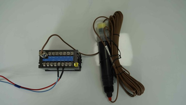
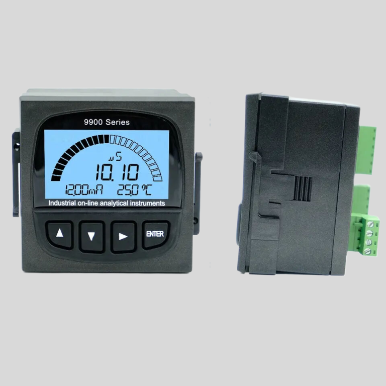
Understanding the Working Principle of a conductivity meter: A Comprehensive Guide
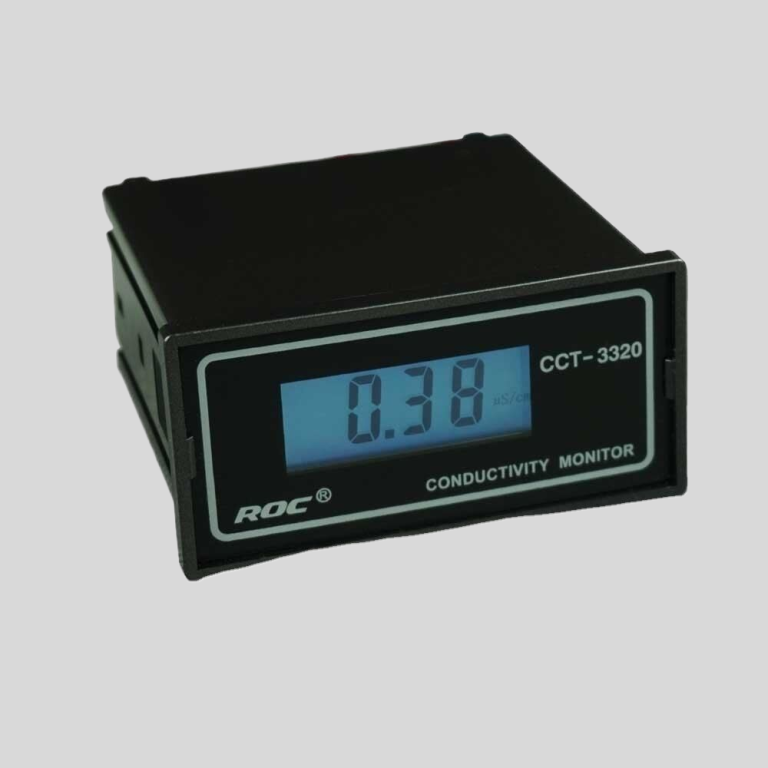
Conductivity meters are essential tools used in various industries to measure the conductivity of a solution. Understanding the working principle of a conductivity meter is crucial for accurate measurements and reliable results. In this comprehensive guide, we will delve into the intricacies of how conductivity meters work and provide a detailed explanation of their operation.
At its core, a conductivity meter measures the ability of a solution to conduct electricity. This ability is directly related to the concentration of ions present in the solution. When an electric current is passed through a solution, the ions in the solution carry the current, allowing it to flow. The conductivity of the solution is determined by the number and mobility of these ions.
The working principle of a conductivity meter is based on the measurement of the electrical conductivity of a solution. The meter consists of two electrodes, typically made of a conductive material such as platinum or graphite, that are immersed in the solution. When a voltage is applied across the electrodes, an electric current flows through the solution. The conductivity meter measures the resistance of the solution to the flow of this current, which is directly related to the conductivity of the solution.
To measure the conductivity of a solution, the conductivity meter uses a technique known as four-electrode conductivity measurement. In this technique, two of the electrodes are used to apply the voltage across the solution, while the other two electrodes are used to measure the resulting current. This allows for more accurate measurements by eliminating the effects of electrode polarization and contact resistance.
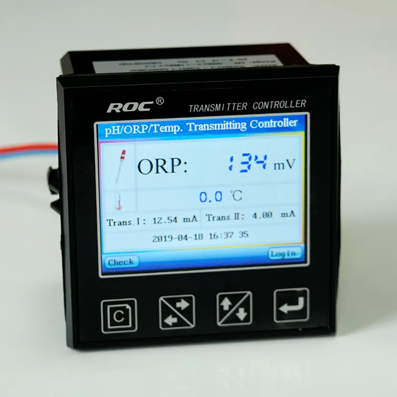
The conductivity meter also compensates for temperature variations, as the conductivity of a solution is highly dependent on temperature. Most conductivity meters are equipped with a temperature sensor that automatically adjusts the measured conductivity value based on the temperature of the solution. This ensures that the measurements are accurate and consistent, regardless of changes in temperature.
In addition to measuring the conductivity of a solution, conductivity meters can also be used to determine the total dissolved solids (TDS) in a solution. TDS is a measure of the total concentration of dissolved substances in a solution, including both ions and non-ionic compounds. By measuring the conductivity of a solution and applying a conversion factor, conductivity meters can calculate the TDS of the solution.
| ROS-8600 RO Program Control HMI Platform | ||
| Model | ROS-8600 Single Stage | ROS-8600 Double Stage |
| Measuring range | Source water0~2000uS/cm | Source water0~2000uS/cm |
| First level effluent 0~200uS/cm | First level effluent 0~200uS/cm | |
| secondary effluent 0~20uS/cm | secondary effluent 0~20uS/cm | |
| Pressure sensor(optional) | Membrane pre/post pressure | Primary/ secondary membrane front/rear pressure |
| ph sensor(optional) | —- | 0~14.00pH |
| Signal collection | 1.Raw water low pressure | 1.Raw water low pressure |
| 2.Primary booster pump inlet low pressure | 2.Primary booster pump inlet low pressure | |
| 3.Primary booster pump outlet high pressure | 3.Primary booster pump outlet high pressure | |
| 4.High liquid level of Level 1 tank | 4.High liquid level of Level 1 tank | |
| 5.Low liquid level of Level 1 tank | 5.Low liquid level of Level 1 tank | |
| 6.Preprocessing signal | 6.2nd booster pump outlet high pressure | |
| 7.Input standby ports x2 | 7.High liquid level of Level 2 tank | |
| 8.Low liquid level of Level 2 tank | ||
| 9.Preprocessing signal | ||
| 10.Input standby ports x2 | ||
| Output control | 1.Water inlet valve | 1.Water inlet valve |
| 2.Source water pump | 2.Source water pump | |
| 3.Primary booster pump | 3.Primary booster pump | |
| 4.Primary flush valve | 4.Primary flush valve | |
| 5.Primary dosing pump | 5.Primary dosing pump | |
| 6.Primary water over standard discharge valve | 6.Primary water over standard discharge valve | |
| 7.Alarm output node | 7.Secondary booster pump | |
| 8.Manual standby pump | 8.Secondary flush valve | |
| 9.Secondary dosing pump | 9.Secondary dosing pump | |
| Output standby port x2 | 10.Secondary water over standard discharge valve | |
| 11.Alarm output node | ||
| 12.Manual standby pump | ||
| Output standby port x2 | ||
| The main function | 1.Correction of electrode constant | 1.Correction of electrode constant |
| 2.Overrun alarm setting | 2.Overrun alarm setting | |
| 3.All working mode time can be set | 3.All working mode time can be set | |
| 4.High and low pressure flushing mode setting | 4.High and low pressure flushing mode setting | |
| 5.The low pressure pump is opened when preprocessing | 5.The low pressure pump is opened when preprocessing | |
| 6.Manual/automatic can be chosen when boot up | 6.Manual/automatic can be chosen when boot up | |
| 7.Manual debugging mode | 7.Manual debugging mode | |
| 8.Alarm if communication interruption | 8.Alarm if communication interruption | |
| 9. Urging payment settings | 9. Urging payment settings | |
| 10. Company name,website can be customized | 10. Company name,website can be customized | |
| Power supply | DC24V±10% | DC24V±10% |
| Expansion interface | 1.Reserved relay output | 1.Reserved relay output |
| 2.RS485 communication | 2.RS485 communication | |
| 3.Reserved IO port, analog module | 3.Reserved IO port, analog module | |
| 4.Mobile/computer/touch screen synchronous display | 4.Mobile/computer/touch screen synchronous display | |
| Relative humidity | ≦85% | ≤85% |
| Environment temperature | 0~50℃ | 0~50℃ |
| Touch screen size | 163x226x80mm (H x W x D) | 163x226x80mm (H x W x D) |
| Hole Size | 7 inch:215*152mm(wide*high) | 215*152mm(wide*high) |
| Controller size | 180*99(long*wide) | 180*99(long*wide) |
| Transmitter size | 92*125(long*wide) | 92*125(long*wide) |
| Installation method | Touch screen:panel embedded; Controller: plane fixed | Touch screen:panel embedded; Controller: plane fixed |
Overall, conductivity meters are versatile instruments that play a crucial role in various industries, including water treatment, pharmaceuticals, and food and beverage production. By understanding the working principle of a conductivity meter, users can ensure accurate measurements and reliable results. Conductivity meters are essential tools for monitoring and controlling the quality of solutions, and their operation is based on the fundamental principles of electrical conductivity.
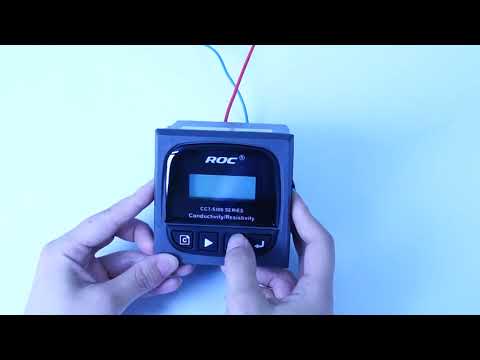
| Model | CCT-5300E series Conductivity/Resistivity/TDS Online Controller |
| Constant | 0.01cm-1, 0.1 cm-1, 1.0cm-1, 10.0 cm-1 |
| Conductivity | (0.5~20,000)uS/cm,(0.5~2,000)uS/cm, (0.5~200)uS/cm, (0.05~18.25)MQ·cm |
| TDS | (0.25~10,000)ppm, (0.25~1,000)ppm, (0.25~100)ppm |
| Medium Temp. | (0~50)℃(Temp.Compensation: NTC10K) |
| Accuracy | Conductivity: 1.5%(FS), Resistivity:2.0%(FS), TDS: 1.5%(FS), Temp.: +/-0.5℃ |
| Temp. compensation | (0-50)°C (with 25℃ as Standard) |
| Cable length | ≤20m(MAX) |
| mA output | Isolated, transportable (4~20)mA, Instrument / Transmitter for selection |
| Control Output | relay contact: ON/OFF, Load capacity: AC 230V/5A(Max) |
| Working Environment | Temp.(0~50)℃;Relative Humidity ≤85%RH (none condensation) |
| Storage Environment | Temp.(-20~60)℃;Relative Humidity ≤85%RH (none condensation) |
| Power Supply | CCT-5300E: DC 24V; CCT-5320E: AC 220V |
| Dimension | 96mmx96mmx105mm(HxWxD) |
| Hole Size | 91mmx91mm(HxW) |
| Installation | Panel mounted, fast installation |

