Table of Contents
How Flow Sensors Work in Dryers
Flow sensors are an essential component in modern dryers, helping to regulate the flow of air and ensure optimal drying performance. These sensors play a crucial role in maintaining the efficiency and effectiveness of the drying process, ultimately leading to better results and energy savings. In this article, we will explore the function of flow sensors in dryers and how they work to improve overall performance.
Flow sensors are devices that measure the flow rate of a fluid, such as air, passing through a system. In the case of dryers, flow sensors are used to monitor the airflow within the dryer drum and exhaust system. By measuring the flow of air, these sensors can help to ensure that the dryer is operating at the correct temperature and humidity levels, which are essential for efficient drying.
One of the key functions of flow sensors in dryers is to prevent overheating. When the airflow within the dryer is restricted or blocked, the temperature inside the drum can rise to dangerous levels, potentially causing damage to the dryer and posing a fire hazard. Flow sensors are designed to detect any abnormalities in airflow and alert the dryer’s control system to take corrective action, such as reducing the heat or shutting off the dryer altogether.
In addition to preventing overheating, flow sensors also help to optimize drying performance. By monitoring the flow of air, these sensors can adjust the drying cycle to ensure that clothes are dried evenly and efficiently. For example, if the airflow is too low, the sensor may increase the drying time to compensate, while if the airflow is too high, the sensor may reduce the drying time to prevent over-drying.
Flow sensors in dryers typically work by measuring the pressure drop across a fixed restriction in the airflow path. As air passes through the restriction, the pressure on one side of the sensor will be higher than on the other side. By measuring this pressure difference, the sensor can calculate the flow rate of air passing through the system. This information is then used to adjust the drying cycle as needed to maintain optimal drying conditions.
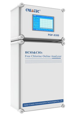
| POP-8300 free chlorine online analyzer | ||
| System Model | POP-8300 free chlorine online analyzer | |
| Measurement configuration | (HClO)free chlorine.. | |
| total free chlorine/(ClO2)/pH/Temperature | ||
| Free chlorine | (0.00-2.00)mg/L(ppm); (0.00-20.00)mg/L(ppm) | |
| Measurement | pH | 2.00-12.00 |
| range | Temperature | (0.0-99.9)℃ |
| Free chlorine | 0.01mg/L(ppm) | |
| Resolution | pH | 0.01 |
| Temperature | 0.1℃ | |
| Free chlorine | Indication error 10% | |
| Accuracy | pH | 0.1pH |
| Temperature | ±0.5℃ | |
| Sensor life | pH/free chlorine sensor | 12months(The service life is closely related to the measurement medium and maintenance frequency) |
| Communication interface | RS485 | MODBUS RTU communication protocol |
| Number of channels | Double channels | |
| (4-20)mA | Technical feature | Isolated, reversible, completely adjustable, instrument/transmitter dual mode |
| output | Channel configuration | Programmable point to Free chlorine, chlorine dioxide, Temperature, pH |
| Loop resistance | 400Ω(Max), DC 24V | |
| Transmission accuracy | ±0.1mA | |
| Number of channels | Double channels | |
| Contact mode | The first and second for photoelectric switch | |
| Control output | Load capacity | Load current 50mA(Max),AC/DC 30V |
| Control point | Programmable function(Free chlorine, chlorine dioxide, Temperature, pH, Timing) | |
| Load capacity | Load current 50mA(Max),AC/DC 30V | |
| Control point | Programmable function(Free chlorine, chlorine dioxide, Temperature, pH, Timing) | |
| Power supply | Connected to electric supply | |
| AC80-260V;50/60Hz,compatible with all international | ||
| market power standards(110V;220V;260V;50/60Hz). | ||
| Working environment | Temperature:(5-50)℃;relative humidity:≤85% RH(non condensation) | |
| Power Consumption | <20W | |
| Storage environment | Temperature:(-20-70)℃;relative humidity:≤85%RH(non condensation) | |
| Installation | Wall mounted(with the preset back cover) | |
| Cabinet weight | ≤10kg | |
| Cabinet dimension | 570*mm*380mm*130mm(H×W×D) | |
In conclusion, flow sensors are a critical component in modern dryers, helping to regulate airflow and ensure efficient drying performance. By monitoring the flow of air, these sensors can prevent overheating, optimize drying performance, and ultimately improve the overall efficiency of the dryer. With their ability to detect abnormalities in airflow and make real-time adjustments to the drying cycle, flow sensors play a vital role in ensuring that clothes are dried quickly and evenly. Whether you are using a gas or electric dryer, flow sensors are an essential part of the system that helps to make the drying process more efficient and effective.
Importance of Flow Sensors in Dryers
Flow sensors are an essential component in modern dryers, playing a crucial role in ensuring efficient and safe operation. These sensors are designed to measure the flow of air or gas within the dryer system, providing valuable data that helps regulate temperature, prevent overheating, and optimize drying performance. In this article, we will explore the importance of flow sensors in dryers and how they contribute to the overall functionality of these appliances.
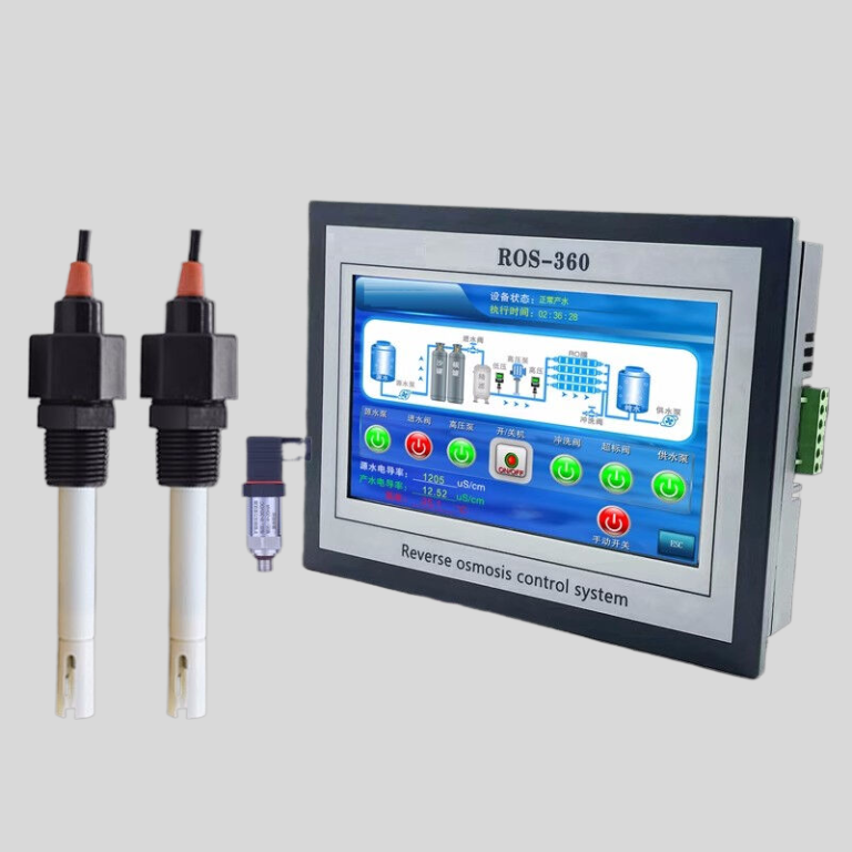
| ROS-8600 RO Program Control HMI Platform | ||
| Model | ROS-8600 Single Stage | ROS-8600 Double Stage |
| Measuring range | Source water0~2000uS/cm | Source water0~2000uS/cm |
| First level effluent 0~200uS/cm | First level effluent 0~200uS/cm | |
| secondary effluent 0~20uS/cm | secondary effluent 0~20uS/cm | |
| Pressure sensor(optional) | Membrane pre/post pressure | Primary/ secondary membrane front/rear pressure |
| ph sensor(optional) | —- | 0~14.00pH |
| Signal collection | 1.Raw water low pressure | 1.Raw water low pressure |
| 2.Primary booster pump inlet low pressure | 2.Primary booster pump inlet low pressure | |
| 3.Primary booster pump outlet high pressure | 3.Primary booster pump outlet high pressure | |
| 4.High liquid level of Level 1 tank | 4.High liquid level of Level 1 tank | |
| 5.Low liquid level of Level 1 tank | 5.Low liquid level of Level 1 tank | |
| 6.Preprocessing signal | 6.2nd booster pump outlet high pressure | |
| 7.Input standby ports x2 | 7.High liquid level of Level 2 tank | |
| 8.Low liquid level of Level 2 tank | ||
| 9.Preprocessing signal | ||
| 10.Input standby ports x2 | ||
| Output control | 1.Water inlet valve | 1.Water inlet valve |
| 2.Source water pump | 2.Source water pump | |
| 3.Primary booster pump | 3.Primary booster pump | |
| 4.Primary flush valve | 4.Primary flush valve | |
| 5.Primary dosing pump | 5.Primary dosing pump | |
| 6.Primary water over standard discharge valve | 6.Primary water over standard discharge valve | |
| 7.Alarm output node | 7.Secondary booster pump | |
| 8.Manual standby pump | 8.Secondary flush valve | |
| 9.Secondary dosing pump | 9.Secondary dosing pump | |
| Output standby port x2 | 10.Secondary water over standard discharge valve | |
| 11.Alarm output node | ||
| 12.Manual standby pump | ||
| Output standby port x2 | ||
| The main function | 1.Correction of electrode constant | 1.Correction of electrode constant |
| 2.Overrun alarm setting | 2.Overrun alarm setting | |
| 3.All working mode time can be set | 3.All working mode time can be set | |
| 4.High and low pressure flushing mode setting | 4.High and low pressure flushing mode setting | |
| 5.The low pressure pump is opened when preprocessing | 5.The low pressure pump is opened when preprocessing | |
| 6.Manual/automatic can be chosen when boot up | 6.Manual/automatic can be chosen when boot up | |
| 7.Manual debugging mode | 7.Manual debugging mode | |
| 8.Alarm if communication interruption | 8.Alarm if communication interruption | |
| 9. Urging payment settings | 9. Urging payment settings | |
| 10. Company name,website can be customized | 10. Company name,website can be customized | |
| Power supply | DC24V±10% | DC24V±10% |
| Expansion interface | 1.Reserved relay output | 1.Reserved relay output |
| 2.RS485 communication | 2.RS485 communication | |
| 3.Reserved IO port, analog module | 3.Reserved IO port, analog module | |
| 4.Mobile/computer/touch screen synchronous display | 4.Mobile/computer/touch screen synchronous display | |
| Relative humidity | ≦85% | ≤85% |
| Environment temperature | 0~50℃ | 0~50℃ |
| Touch screen size | 163x226x80mm (H x W x D) | 163x226x80mm (H x W x D) |
| Hole Size | 7 inch:215*152mm(wide*high) | 215*152mm(wide*high) |
| Controller size | 180*99(long*wide) | 180*99(long*wide) |
| Transmitter size | 92*125(long*wide) | 92*125(long*wide) |
| Installation method | Touch screen:panel embedded; Controller: plane fixed | Touch screen:panel embedded; Controller: plane fixed |
One of the primary functions of a flow sensor in a dryer is to monitor the airflow within the system. By measuring the rate at which air or gas is moving through the dryer, the sensor can help maintain a consistent temperature throughout the drying process. This is particularly important in gas dryers, where an imbalance in airflow can lead to inefficient heating and potential safety hazards. Flow sensors help ensure that the burner is receiving an adequate supply of gas, preventing issues such as incomplete combustion or carbon monoxide buildup.
In addition to regulating temperature, flow sensors also play a key role in preventing overheating in dryers. By monitoring the flow of air or gas, these sensors can detect any obstructions or blockages in the system that may impede proper ventilation. If airflow is restricted, the sensor can trigger an alarm or shut off the dryer altogether to prevent overheating and potential fire hazards. This level of safety monitoring is essential in preventing accidents and ensuring the longevity of the appliance.
Furthermore, flow sensors help optimize drying performance by providing real-time data on the efficiency of the drying process. By measuring the flow of air or gas, these sensors can determine if the dryer is operating at peak efficiency or if adjustments need to be made to improve performance. This information can be used to fine-tune the settings of the dryer, such as adjusting the temperature or cycle time, to achieve optimal drying results. By continuously monitoring airflow, flow sensors help ensure that clothes are dried quickly and evenly, saving time and energy in the process.
Overall, flow sensors are a critical component in modern dryers, providing essential data that helps regulate temperature, prevent overheating, and optimize drying performance. These sensors play a key role in maintaining the safety and efficiency of the appliance, ensuring that clothes are dried quickly and evenly without the risk of overheating or fire hazards. As technology continues to advance, flow sensors will likely become even more sophisticated, offering greater precision and control over the drying process. In conclusion, flow sensors are an indispensable tool in the world of dryers, helping to make laundry day a little bit easier and safer for everyone.

