Determining the Optimal Calibration Range for DP Flow Transmitter
In the world of process control and instrumentation, differential pressure (DP) flow transmitters play a crucial role in accurately measuring the flow of liquids and gases in various industrial applications. These transmitters work by measuring the pressure difference between two points in a pipe or duct, which is then used to calculate the flow rate. However, in order for DP flow transmitters to provide accurate and reliable measurements, they must be properly calibrated.
Calibration is the process of adjusting a measuring instrument to ensure that it provides accurate and consistent readings. When it comes to DP flow transmitters, one of the key factors to consider during calibration is the calibration range. The calibration range refers to the span of flow rates over which the transmitter is calibrated to provide accurate measurements. Determining the optimal calibration range for a DP flow transmitter is essential to ensure that it operates within its specified accuracy limits and provides reliable data.
When selecting the calibration range for a DP flow transmitter, it is important to consider the expected operating conditions of the system in which it will be used. The calibration range should cover the full range of flow rates that the transmitter is likely to encounter during normal operation. This ensures that the transmitter will be able to accurately measure flow rates across the entire operating range of the system.
| Model No. | CCT-8301A Conductivity Resistivity Online Controller Spec | |||
| Conductivity | Resistivity | TDS | Temp. | |
| Measurement range | 0.1μS/cm~40.0mS/cm | 50KΩ·cm~18.25MΩ·cm | 0.25ppm~20ppt | (0~100)℃ |
| Resolution | 0.01μS/cm | 0.01MΩ·cm | 0.01ppm | 0.1℃ |
| Accuracy | 1.5level | 2.0level | 1.5level | ±0.5℃ |
| Temp.Compensation | Pt1000 | |||
| Working Environment | Temp. (0~50)℃; relative humidity ≤85%RH | |||
| Analog Output | Double channel (4~20)mA,Instrument/Transmitter for selection | |||
| Control Output | Triple channels photo-electronic semiconductor relay ,Load capacity: AC/DC 30V,50mA(max) | |||
| Power Supply | DC 24V±15% | |||
| Consumption | ≤4W | |||
| Protection Level | IP65(with the back cover) | |||
| Installation | Panel mounted | |||
| Dimension | 96mm×96mm×94mm (H×W×D) | |||
| Hole Size | 91mm×91mm(H×W) | |||
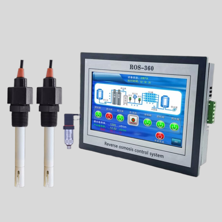
| ROS-8600 RO Program Control HMI Platform | ||
| Model | ROS-8600 Single Stage | ROS-8600 Double Stage |
| Measuring range | Source water0~2000uS/cm | Source water0~2000uS/cm |
| First level effluent 0~200uS/cm | First level effluent 0~200uS/cm | |
| secondary effluent 0~20uS/cm | secondary effluent 0~20uS/cm | |
| Pressure sensor(optional) | Membrane pre/post pressure | Primary/ secondary membrane front/rear pressure |
| ph sensor(optional) | —- | 0~14.00pH |
| Signal collection | 1.Raw water low pressure | 1.Raw water low pressure |
| 2.Primary booster pump inlet low pressure | 2.Primary booster pump inlet low pressure | |
| 3.Primary booster pump outlet high pressure | 3.Primary booster pump outlet high pressure | |
| 4.High liquid level of Level 1 tank | 4.High liquid level of Level 1 tank | |
| 5.Low liquid level of Level 1 tank | 5.Low liquid level of Level 1 tank | |
| 6.Preprocessing signal | 6.2nd booster pump outlet high pressure | |
| 7.Input standby ports x2 | 7.High liquid level of Level 2 tank | |
| 8.Low liquid level of Level 2 tank | ||
| 9.Preprocessing signal | ||
| 10.Input standby ports x2 | ||
| Output control | 1.Water inlet valve | 1.Water inlet valve |
| 2.Source water pump | 2.Source water pump | |
| 3.Primary booster pump | 3.Primary booster pump | |
| 4.Primary flush valve | 4.Primary flush valve | |
| 5.Primary dosing pump | 5.Primary dosing pump | |
| 6.Primary water over standard discharge valve | 6.Primary water over standard discharge valve | |
| 7.Alarm output node | 7.Secondary booster pump | |
| 8.Manual standby pump | 8.Secondary flush valve | |
| 9.Secondary dosing pump | 9.Secondary dosing pump | |
| Output standby port x2 | 10.Secondary water over standard discharge valve | |
| 11.Alarm output node | ||
| 12.Manual standby pump | ||
| Output standby port x2 | ||
| The main function | 1.Correction of electrode constant | 1.Correction of electrode constant |
| 2.Overrun alarm setting | 2.Overrun alarm setting | |
| 3.All working mode time can be set | 3.All working mode time can be set | |
| 4.High and low pressure flushing mode setting | 4.High and low pressure flushing mode setting | |
| 5.The low pressure pump is opened when preprocessing | 5.The low pressure pump is opened when preprocessing | |
| 6.Manual/automatic can be chosen when boot up | 6.Manual/automatic can be chosen when boot up | |
| 7.Manual debugging mode | 7.Manual debugging mode | |
| 8.Alarm if communication interruption | 8.Alarm if communication interruption | |
| 9. Urging payment settings | 9. Urging payment settings | |
| 10. Company name,website can be customized | 10. Company name,website can be customized | |
| Power supply | DC24V±10% | DC24V±10% |
| Expansion interface | 1.Reserved relay output | 1.Reserved relay output |
| 2.RS485 communication | 2.RS485 communication | |
| 3.Reserved IO port, analog module | 3.Reserved IO port, analog module | |
| 4.Mobile/computer/touch screen synchronous display | 4.Mobile/computer/touch screen synchronous display | |
| Relative humidity | ≦85% | ≤85% |
| Environment temperature | 0~50℃ | 0~50℃ |
| Touch screen size | 163x226x80mm (H x W x D) | 163x226x80mm (H x W x D) |
| Hole Size | 7 inch:215*152mm(wide*high) | 215*152mm(wide*high) |
| Controller size | 180*99(long*wide) | 180*99(long*wide) |
| Transmitter size | 92*125(long*wide) | 92*125(long*wide) |
| Installation method | Touch screen:panel embedded; Controller: plane fixed | Touch screen:panel embedded; Controller: plane fixed |
In addition to considering the expected operating conditions, it is also important to take into account the accuracy requirements of the application. Different applications may have different accuracy requirements, and the calibration range should be selected to meet these requirements. For example, in applications where precise flow measurements are critical, a narrower calibration range with a higher level of accuracy may be necessary.
It is also important to consider the resolution of the transmitter when selecting the calibration range. The resolution refers to the smallest change in flow rate that the transmitter can detect. A calibration range that is too wide may result in reduced resolution, making it difficult to accurately measure small changes in flow rate. On the other hand, a calibration range that is too narrow may limit the range of flow rates that the transmitter can accurately measure.
In conclusion, determining the optimal calibration range for a DP flow transmitter is essential to ensure accurate and reliable flow measurements. By considering factors such as expected operating conditions, accuracy requirements, turndown ratio, and resolution, it is possible to select a calibration range that meets the needs of the application. Proper calibration of DP flow transmitters is crucial to ensuring the efficiency and effectiveness of industrial processes that rely on accurate flow measurements.
