Importance of Calibration in conductivity meter
Calibration is a critical process in ensuring the accuracy and reliability of conductivity meters. Conductivity meters are used in various industries, including pharmaceuticals, food and beverage, water treatment, and environmental monitoring, to measure the conductivity of a solution. The calibration of a conductivity meter involves adjusting the instrument to ensure that it provides accurate and precise measurements.
Calibration also helps to ensure the reliability of conductivity meters. By calibrating the instrument regularly, users can have confidence in the accuracy of the measurements and trust that the results are consistent and repeatable. This is especially important in industries where quality control and compliance with regulations are paramount.
In addition to accuracy and reliability, calibration also helps to extend the lifespan of conductivity meters. Regular calibration can help to identify any issues with the instrument early on, allowing for timely maintenance and repairs. This can prevent costly downtime and ensure that the conductivity meter continues to perform optimally for an extended period.
It is recommended that conductivity meters be calibrated at least once a year, or more frequently if the instrument is used frequently or in harsh conditions. Some industries may have specific regulations or guidelines regarding the frequency of calibration, so it is important to follow these recommendations to ensure compliance.
| ROS-8600 RO Program Control HMI Platform | ||
| Model | ROS-8600 Single Stage | ROS-8600 Double Stage |
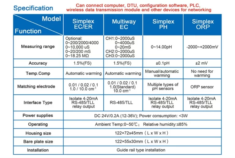
| Measuring range | Source water0~2000uS/cm | Source water0~2000uS/cm |
| First level effluent 0~200uS/cm | First level effluent 0~200uS/cm | |
| secondary effluent 0~20uS/cm | secondary effluent 0~20uS/cm | |
| Pressure sensor(optional) | Membrane pre/post pressure | Primary/ secondary membrane front/rear pressure |
| ph sensor(optional) | —- | 0~14.00pH |
| Signal collection | 1.Raw water low pressure | 1.Raw water low pressure |
| 2.Primary booster pump inlet low pressure | 2.Primary booster pump inlet low pressure | |
| 3.Primary booster pump outlet high pressure | 3.Primary booster pump outlet high pressure | |
| 4.High liquid level of Level 1 tank | 4.High liquid level of Level 1 tank | |
| 5.Low liquid level of Level 1 tank | 5.Low liquid level of Level 1 tank | |
| 6.Preprocessing signal | 6.2nd booster pump outlet high pressure | |
| 7.Input standby ports x2 | 7.High liquid level of Level 2 tank | |
| 8.Low liquid level of Level 2 tank | ||
| 9.Preprocessing signal | ||
| 10.Input standby ports x2 | ||
| Output control | 1.Water inlet valve | 1.Water inlet valve |
| 2.Source water pump | 2.Source water pump | |
| 3.Primary booster pump | 3.Primary booster pump | |
| 4.Primary flush valve | 4.Primary flush valve | |
| 5.Primary dosing pump | 5.Primary dosing pump | |
| 6.Primary water over standard discharge valve | 6.Primary water over standard discharge valve | |
| 7.Alarm output node | 7.Secondary booster pump | |
| 8.Manual standby pump | 8.Secondary flush valve | |
| 9.Secondary dosing pump | 9.Secondary dosing pump | |
| Output standby port x2 | 10.Secondary water over standard discharge valve | |
| 11.Alarm output node | ||
| 12.Manual standby pump | ||
| Output standby port x2 | ||
| The main function | 1.Correction of electrode constant | 1.Correction of electrode constant |
| 2.Overrun alarm setting | 2.Overrun alarm setting | |
| 3.All working mode time can be set | 3.All working mode time can be set | |
| 4.High and low pressure flushing mode setting | 4.High and low pressure flushing mode setting | |
| 5.The low pressure pump is opened when preprocessing | 5.The low pressure pump is opened when preprocessing | |
| 6.Manual/automatic can be chosen when boot up | 6.Manual/automatic can be chosen when boot up | |
| 7.Manual debugging mode | 7.Manual debugging mode | |
| 8.Alarm if communication interruption | 8.Alarm if communication interruption | |
| 9. Urging payment settings | 9. Urging payment settings | |
| 10. Company name,website can be customized | 10. Company name,website can be customized | |
| Power supply | DC24V±10% | DC24V±10% |
| Expansion interface | 1.Reserved relay output | 1.Reserved relay output |
| 2.RS485 communication | 2.RS485 communication | |
| 3.Reserved IO port, analog module | 3.Reserved IO port, analog module | |
| 4.Mobile/computer/touch screen synchronous display | 4.Mobile/computer/touch screen synchronous display | |
| Relative humidity | ≦85% | ≤85% |
| Environment temperature | 0~50℃ | 0~50℃ |
| Touch screen size | 163x226x80mm (H x W x D) | 163x226x80mm (H x W x D) |
| Hole Size | 7 inch:215*152mm(wide*high) | 215*152mm(wide*high) |
| Controller size | 180*99(long*wide) | 180*99(long*wide) |
| Transmitter size | 92*125(long*wide) | 92*125(long*wide) |
| Installation method | Touch screen:panel embedded; Controller: plane fixed | Touch screen:panel embedded; Controller: plane fixed |
The calibration process for conductivity meters typically involves using calibration solutions with known conductivity values to adjust the instrument. The calibration solutions are usually made of standard substances such as potassium chloride or sodium chloride, which have well-defined conductivity values. By comparing the readings of the conductivity meter with the known values of the calibration solutions, adjustments can be made to ensure that the instrument is providing accurate measurements.
It is important to follow the manufacturer’s instructions when calibrating a conductivity meter to ensure that the process is done correctly. This may involve adjusting the instrument’s settings, cleaning the electrodes, or performing other maintenance tasks. It is also important to record the calibration results and keep a log of when the instrument was calibrated and any adjustments that were made.
| FL-9900 High Precision Type Runner Flow Controller | ||
| Measuring range | Frequency | 0~2K Hz |
| Velocity of flow | 0.5~5 m/s | |
| Instantaneous flow | 0~2000 m³/h | |
| Cumulative flow | 0~9999 9999.999 m³ | |
| Applicable pipe diameter range | DN15~DN100;DN125~DN300 | |
| Resolution | 0.01 m³/h | |
| Refresh rate | 1s | |
| Accuracy class | Level 2.0 | |
| Repeatability | ±0.5% | |
| Sensor input | Radius:0~2K Hz | |
| Supply voltage:DC 24V(instrument internal supply) | ||
| The electronic unit automatically temperature compensates for errors | +0.5%FS; | |
| 4-20mA | Technical characteristics | Meter/transmitter dual mode (photoelectric isolation) |
| Loop resistance | 500Q(max),DC24V; | |
| Transmission accuracy | ±0.01mA | |
| Control port | Contact mode | Passive relay control output |
| Load capacity | Load current 5A (max) | |
| Function selection | Instantaneous flow upper/lower alarm | |
| Mains supply | Working voltage: DC24V 4V Power consumption :<; 3.OW | |
| Cable length | Factory configuration: 5m, can be agreed: (1~500) m | |
| Environmental requirement | Temperature: 0~50℃; Relative humidity: ≤85%RH | |
| Storage environment | Temperature: (-20~60) ℃; Humidity: 85%RH | |
| Overall dimension | 96×96×72mm(height × width × depth) | |
| Opening size | 92×92mm | |
| Installation mode | Disc mounted, fast fixed | |
| Sensor | Body material | Body: Engineering plastic PP; Bearing :Zr02 high temperature zirconia |
| Flow rate range | 0.5~5 m/s | |
| Withstand pressure | ≤0.6MPa | |
| Supply voltage | lDC 24V | |
| Output pulse amplitude| | Vp≥8V | |
| Normal pipe diameter | DN15~DN100;DN125~DN600 | |
| Medium characteristic | Single-phase medium(0~60℃) | |
| Installation mode | Direct line insertion | |
In conclusion, calibration is a crucial process in ensuring the accuracy, reliability, and longevity of conductivity meters. By calibrating the instrument regularly and following the manufacturer’s instructions, users can have confidence in the measurements provided by the conductivity meter and ensure that it continues to perform optimally. Regular calibration is essential for industries where precise measurements are critical, and it is important to prioritize this process to maintain the quality and integrity of the measurements.