“Measure, monitor, and manage surface resistivity with precision.”
Understanding the Basics of Surface Resistivity
Surface resistivity meters are essential tools for measuring the electrical resistance of a material’s surface. Understanding how to properly use a surface resistivity meter is crucial for obtaining accurate and reliable measurements. In this article, we will discuss the basics of surface resistivity and provide a step-by-step guide on how to use a surface resistivity meter effectively.
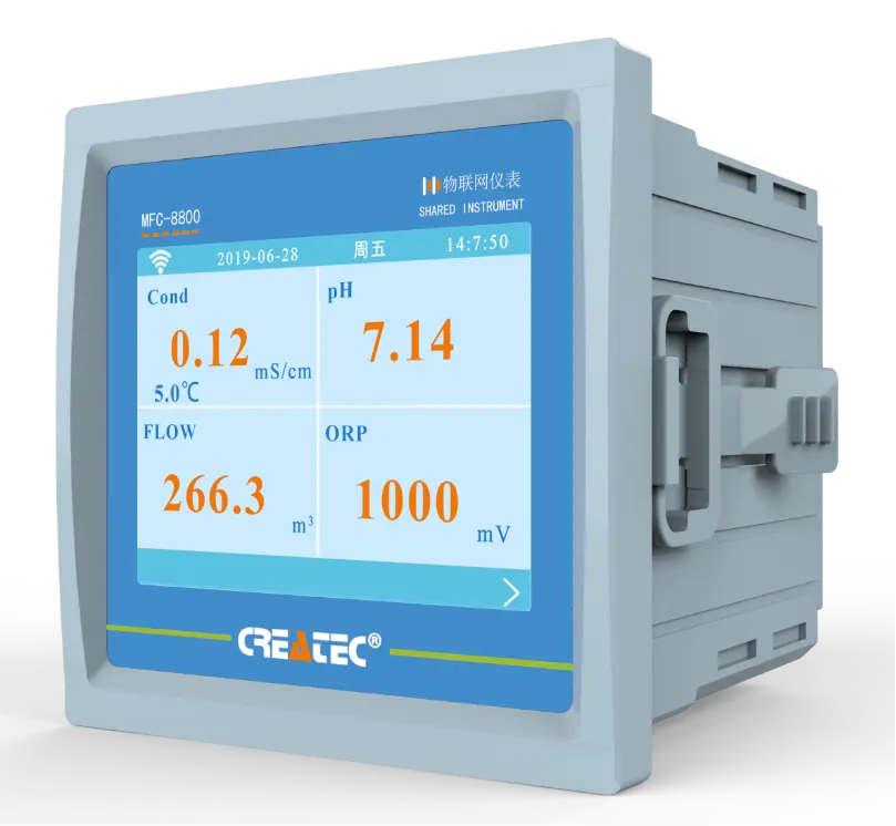
To measure surface resistivity, a surface resistivity meter is used. These meters are designed to apply a known voltage to the material’s surface and measure the resulting current flow. By calculating the ratio of voltage to current, the surface resistivity of the material can be determined.
Before using a surface resistivity meter, it is important to ensure that the meter is calibrated and functioning properly. Calibration should be performed regularly to maintain accuracy. Additionally, the surface of the material being tested should be clean and free of any contaminants that could affect the measurement.
To use a surface resistivity meter, start by connecting the meter to a power source and selecting the appropriate measurement range. Place the meter probe on the surface of the material and apply a known voltage. The meter will then display the measured current flow, which can be used to calculate the surface resistivity.| Model | NTU-1800 Online Turbidity Tester |
| Range | 0-10/100/4000NTU or as required |
| Display | LCD |
| Unit | NTU |
| DPI | 0.01 |
| Accuracy | ±5% FS |
| Repeatability | ±1% |
| Power | ≤3W |
| Power Supply | AC 85V-265V±10% 50/60Hz or |
| DC 9~36V/0.5A | |
| Working Environment | Ambient temperature:0~50℃; |
| Relative humidity≤85% | |
| Dimensions | 160*80*135mm(Hanging) or 96*96mm(Embeded) |
| Communication | 4~20mA and RS-485 communication (Modbus RTU) |
| Switched output | Three-way relay,capacity 250VAC/5A |
When using a surface resistivity meter, it is important to take multiple measurements at different locations on the material’s surface to ensure accuracy. Additionally, it is recommended to perform measurements under different environmental conditions, such as temperature and humidity, to account for any variations in surface resistivity.
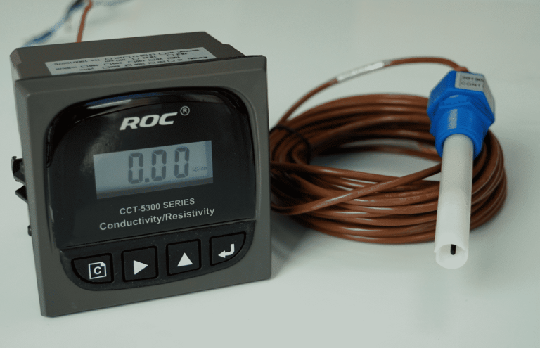
| Model | EC-8851/EC-9900 High Precision Conductivity/resistivity controller |
| Range | 0-200/2000/4000/10000uS/cm |
| 0-20/200mS/cm 0-18.25MΩ | |
| Accuracy | Conductivity:1.5%; Resistivity:2.0%(FS) |
| Temp. Comp. | Automatic temperature compensation based on 25℃ |
| Oper. Temp. | Normal 0~50℃; High temp 0~120℃ |
| Sensor | 0.01/0.02/0.1/1.0/10.0cm-1 |
| Display | LCD Screen |
| Current Output | 4-20mA output/2-10V/1-5V |
| Output | High/Low limit dual relay control |
| Power | DC24V/0.5A or |
| AC85-265V±10% 50/60Hz | |
| Working Environment | Ambient temperature:0~50℃ |
| Relative humidity≤85% | |
| Dimensions | 96×96×72mm(H×W×L) |
| Hole Size | 92×92mm(H×W) |
| Installation Mode | Embedded |
Interpreting the results of a surface resistivity measurement requires an understanding of the material being tested and its intended application. A low surface resistivity indicates that the material is conductive and may not be suitable for certain applications, such as insulating materials. Conversely, a high surface resistivity suggests that the material is insulating and may be suitable for applications requiring electrical isolation.
In conclusion, surface resistivity meters are valuable tools for measuring the electrical resistance of a material’s surface. By following the steps outlined in this article and ensuring proper calibration and measurement techniques, accurate and reliable surface resistivity measurements can be obtained. Understanding the basics of surface resistivity and how to use a surface resistivity meter effectively is essential for ensuring the quality and performance of materials in various industries.

