Understanding the Basics of Conductivity Meters
Conductivity meters are essential tools used in various industries to measure the ability of a solution to conduct electricity. This measurement is crucial in determining the purity and concentration of a solution, as well as monitoring the overall quality of water in different applications. Understanding how conductivity meters work is fundamental to utilizing them effectively and obtaining accurate results.
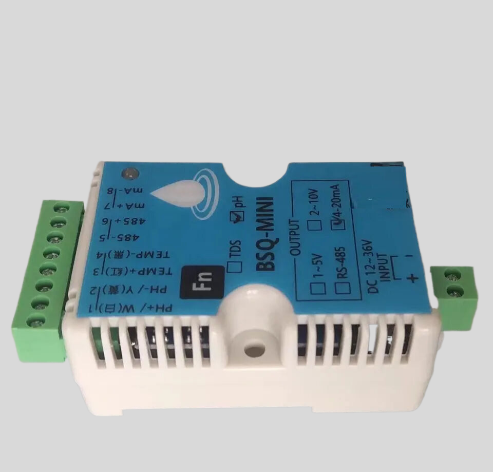
At the core of a conductivity meter is a pair of electrodes that are immersed in the solution being tested. These electrodes are typically made of materials that conduct electricity well, such as platinum or graphite. When an electric current is applied to the electrodes, ions in the solution move towards the electrodes, creating a flow of electricity. The conductivity meter measures this flow of electricity, which is directly proportional to the conductivity of the solution.
One key factor that affects the conductivity of a solution is the concentration of ions present in the solution. Solutions with a higher concentration of ions will conduct electricity more effectively than solutions with a lower ion concentration. This is why conductivity meters are commonly used to measure the concentration of dissolved salts in water, as well as to monitor the purity of various chemical solutions.
In addition to ion concentration, temperature also plays a significant role in the conductivity of a solution. As the temperature of a solution increases, the movement of ions becomes more rapid, leading to an increase in conductivity. To account for this temperature dependency, most conductivity meters are equipped with temperature sensors that automatically compensate for changes in temperature, ensuring accurate and reliable measurements.
Conductivity meters are available in different types, ranging from simple handheld devices to more advanced laboratory-grade instruments. Handheld conductivity meters are portable and easy to use, making them ideal for field measurements and on-site testing. These meters typically display conductivity readings in units of microsiemens per centimeter (µS/cm) or millisiemens per centimeter (mS/cm), depending on the conductivity range being measured.
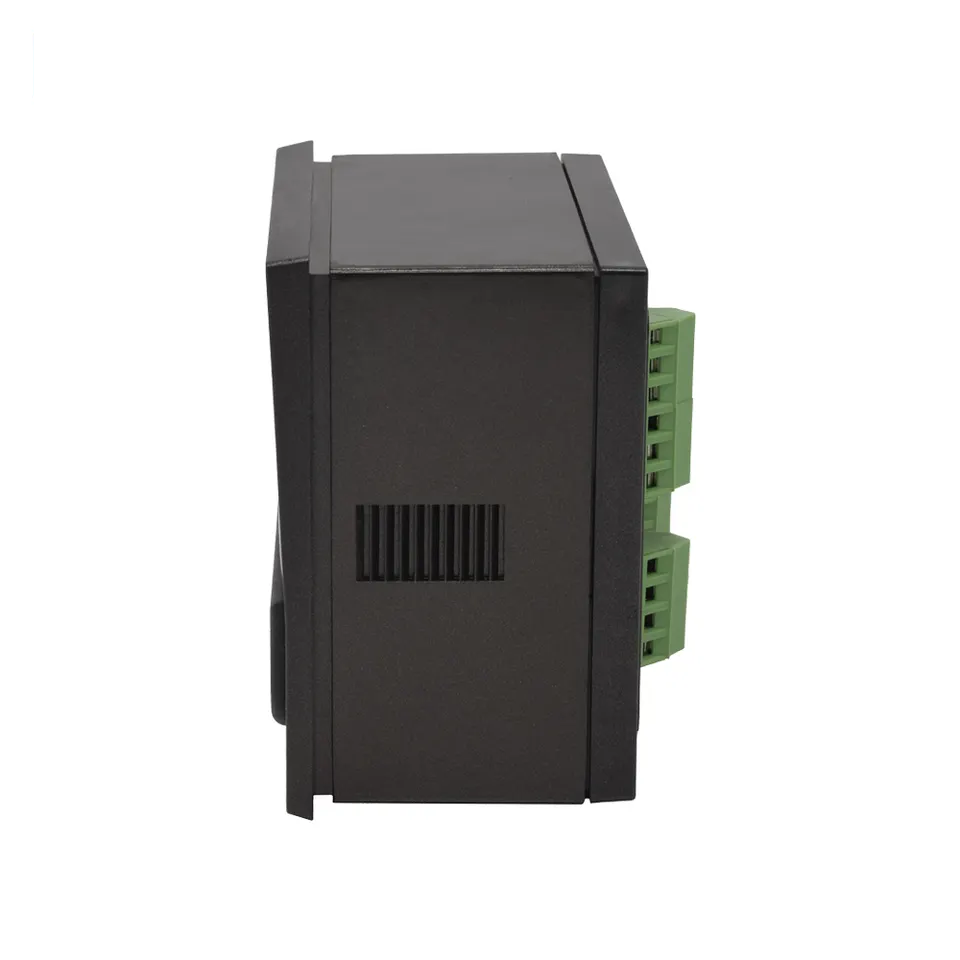
Laboratory-grade conductivity meters, on the other hand, offer higher accuracy and precision, making them suitable for more demanding applications where precise measurements are required. These meters often come with additional features such as data logging, calibration options, and connectivity to external devices for data transfer and analysis.
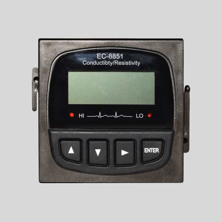
| Model | EC-510 Intelligent conductivity meter |
| Range | 0-200/2000/4000/10000uS/cm |
| 0-18.25MΩ | |
| Accuracy | 1.5%(FS) |
| Temp. Comp. | Automatic temperature compensation |
| Oper. Temp. | Normal 0~50℃; High temp 0~120℃ |
| Sensor | C=0.01/0.02/0.1/1.0/10.0cm-1 |
| Display | LCD Screen |
| Communication | 4-20mA output/2-10V/1-5V/RS485 |
| Output | High/Low limit dual relay control |
| Power | AC 220V±10% 50/60Hz or AC 110V±10% 50/60Hz or DC24V/0.5A |
| Working Environment | Ambient temperature:0~50℃ |
| Relative humidity≤85% | |
| Dimensions | 48×96×100mm(H×W×L) |
| Hole Size | 45×92mm(H×W) |
| Installation Mode | Embedded |
Calibrating a conductivity meter is essential to ensure accurate and reliable measurements. Most conductivity meters can be calibrated using standard calibration solutions with known conductivity values. By immersing the electrodes in a calibration solution and adjusting the meter to match the expected conductivity value, users can verify the accuracy of their meter and make any necessary adjustments.
| Instrument model | FET-8920 | |
| Measurement range | Instantaneous flow | (0~2000)m3/h |
| Accumulative flow | (0~99999999)m3 | |
| Flow rate | (0.5~5)m/s | |
| Resolution | 0.001m3/h | |
| Accuracy level | Less than 2.5% RS or 0.025m/s.whichever is the largest | |
| Conductivity | >20μS/cm | |
| (4~20)mA output | Number of channels | Single channel |
| Technical features | Isolated,reversible,adjustable, meter/transmission dual mode | |
| Loop resistance | 400Ω(Max), DC 24V | |
| Transmission accuracy | ±0.1mA | |
| Control output | Number of channels | Single channel |
| Electrical contact | Semiconductor photoelectric relay | |
| Load capacity | 50mA(Max), DC 30V | |
| Control mode | Instantaneous amount upper/lower limit alarm | |
| Digital output | RS485(MODBUS protocol ),Impulse output1KHz | |
| Working power | Power supply | DC 9~28V |
| source | Power Consumption | ≤3.0W |
| Diameter | DN40~DN300(can be customized) | |
| Working environment | Temperature:(0~50) ℃; Relative humidity: ≤85%RH(none condensation) | |
| Storage environment | Temperature:(-20~60) ℃; Relative humidity: ≤85%RH(none condensation) | |
| Protection grade | IP65 | |
| Installation method | Insertion pipeline installation | |
In conclusion, conductivity meters are valuable tools for measuring the conductivity of solutions in various industries. By understanding how conductivity meters work and the factors that influence conductivity measurements, users can effectively utilize these instruments to monitor the quality of water, assess the purity of chemical solutions, and ensure the accuracy of their measurements. Whether in the field or the laboratory, conductivity meters play a crucial role in maintaining quality control and ensuring the reliability of industrial processes.

