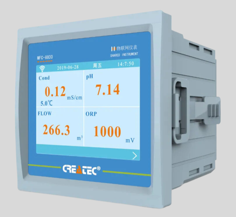
“Measure with precision, test conductivity with ease.”
Table of Contents
Testing Conductivity of Water with a Multimeter
Conductivity is a crucial property of water that measures its ability to conduct electricity. It is an important parameter in various industries, including water treatment, environmental monitoring, and chemical processing. Conductivity is influenced by the presence of ions in water, which can come from dissolved salts, acids, bases, or other substances. Measuring conductivity can help determine the purity of water and identify any contaminants present.
One common method for testing conductivity is using a multimeter. A multimeter is a versatile tool that can measure various electrical properties, including conductivity. To test for conductivity with a multimeter, you will need a few basic materials: a multimeter, two test leads with alligator clips, and a sample of water to test.
To begin the conductivity test, set your multimeter to the conductivity or resistance mode. This mode is usually denoted by the symbol for ohms (Ω). Next, connect the test leads to the multimeter. The black test lead should be connected to the COM (common) port, while the red test lead should be connected to the port labeled for measuring resistance or conductivity.
Once the multimeter is set up, you can start testing the conductivity of water. Fill a container with the water sample you want to test. Make sure the container is clean and free of any contaminants that could affect the conductivity measurement. Submerge the two test leads into the water, ensuring that they are not touching each other.
The multimeter will display a resistance value, which is inversely proportional to conductivity. The lower the resistance value, the higher the conductivity of the water. If the resistance value is too high or the multimeter displays an error message, it may indicate that the water sample is not conductive or that there is an issue with the test setup.
To ensure accurate results, it is essential to calibrate the multimeter before conducting the conductivity test. This can be done by using a known standard solution with a specific conductivity value. By comparing the measured resistance of the standard solution with the expected value, you can verify the accuracy of the multimeter and make any necessary adjustments.
When testing the conductivity of water with a multimeter, it is important to consider the temperature of the water. Conductivity is temperature-dependent, so it is recommended to measure the water temperature and compensate for any variations in conductivity due to temperature changes. Most multimeters have a built-in temperature compensation feature that can automatically adjust the conductivity readings based on the water temperature.
In conclusion, testing conductivity with a multimeter is a simple and effective method for measuring the electrical properties of water. By following the steps outlined above and ensuring proper calibration and temperature compensation, you can accurately determine the conductivity of water samples. Conductivity testing is an essential tool for assessing water quality and identifying any potential contaminants that may be present. With the right equipment and techniques, you can confidently test the conductivity of water and make informed decisions about its use and treatment.
Conductivity Testing of Metals using a Multimeter
Conductivity testing is an essential process in determining the electrical properties of a material. When it comes to metals, conductivity testing is particularly important as it helps in identifying the quality and purity of the metal. One of the most common tools used for conductivity testing is a multimeter. In this article, we will discuss how to test for conductivity with a multimeter.
Before we delve into the testing process, it is important to understand what conductivity is. Conductivity is the ability of a material to conduct electricity. Metals are known for their high conductivity, which makes them ideal for electrical applications. By testing the conductivity of a metal, you can determine its suitability for a particular use.
To test for conductivity with a multimeter, you will need a few basic tools. First and foremost, you will need a multimeter. A multimeter is a versatile tool that can measure various electrical properties, including conductivity. You will also need a piece of metal that you want to test, as well as a pair of test leads that come with the multimeter.
To begin the testing process, set your multimeter to the conductivity testing mode. This mode is usually denoted by a symbol that looks like a sound wave or a series of vertical lines. Once you have selected the conductivity testing mode, connect the test leads to the multimeter. The black lead should be connected to the COM port, while the red lead should be connected to the port labeled with the conductivity symbol.
| Product Model | DOF-6310 (DOF-6141) |
| Product Name | Dissolved oxygen data collection terminal |
| Measuring Method | Fluorescence Method |
| Measurement range | 0-20mg/L |
| Accuracy | ±0.3mg/L |
| Resolution | 0.01mg/L |
| Response time | 90s |
| Repeatibility | 5%RS |
| Temperature compensation | 0-60.0℃ Accuracy:±0.5℃ |
| Air pressure compensation | 300-1100hPa |
| Stand pressure | 0.3Mpa |
| Communication | RS485 MODBUS-RTU standard protocol |
| Power | DC(9-28)V |
| Power comsuption | <2W |
| Operational envrionment | Temperature:(0-50)℃ |
| Storage Environment | Temperature:(-10-60)℃; Humidity:≤95%RH(None condensation) |
| Installation | Submerged |
| Protection Level | IP68 |
| Weight | 1.5Kg(with 10m cable) |
Next, place the test leads on the metal that you want to test. Make sure that the test leads are making good contact with the metal surface. The multimeter will then display a reading that indicates the conductivity of the metal. A low reading indicates poor conductivity, while a high reading indicates good conductivity.
It is important to note that conductivity testing with a multimeter is a qualitative rather than a quantitative measurement. This means that the multimeter will give you a general idea of the metal’s conductivity but will not provide an exact measurement. For more precise measurements, specialized equipment may be required.
In addition to testing the conductivity of a metal, a multimeter can also be used to test for continuity. Continuity testing is a process that checks if there is a complete path for electricity to flow through a material. This is particularly useful when testing for breaks or faults in electrical circuits.
To perform a continuity test with a multimeter, set the multimeter to the continuity testing mode. This mode is usually denoted by a symbol that looks like a diode or a series of horizontal lines. Connect the test leads to the multimeter as before and place them on the metal surface. If there is continuity, the multimeter will emit a sound or display a reading indicating that there is a complete path for electricity to flow.
In conclusion, conductivity testing with a multimeter is a simple yet effective way to determine the electrical properties of a metal. By following the steps outlined in this article, you can quickly and easily test the conductivity of a metal using a multimeter. Conductivity testing is an important process in ensuring the quality and suitability of metals for various applications.
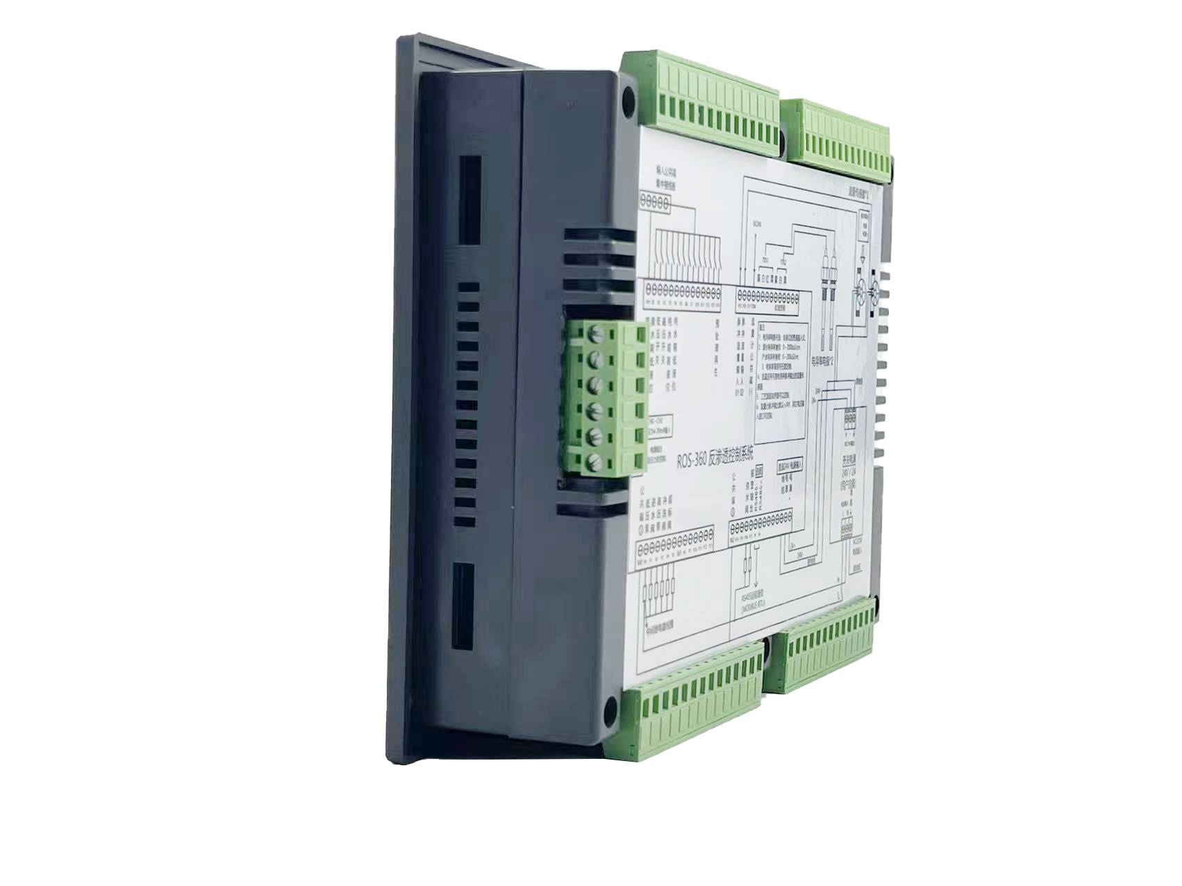
| ROS-360 Water Treatment RO Programmer Controller | ||
| Model | ROS-360 Single Stage | ROS-360 Double Stage |
| Measuring range | Source water0~2000uS/cm | Source water0~2000uS/cm |
| First level effluent 0~1000uS/cm | First level effluent 0~1000uS/cm | |
| secondary effluent 0~100uS/cm | secondary effluent 0~100uS/cm | |
| Pressure sensor(optional) | Membrane pre/post pressure | Primary/ secondary membrane front/rear pressure |
| Flow Sensor(optional) | 2 channels (Inlet/outlet flow rate) | 3 channels (source water, primary flow,secondary flow) |
| IO input | 1.Raw water low pressure | 1.Raw water low pressure |
| 2.Primary booster pump inlet low pressure | 2.Primary booster pump inlet low pressure | |
| 3.Primary booster pump outlet high pressure | 3.Primary booster pump outlet high pressure | |
| 4.High liquid level of Level 1 tank | 4.High liquid level of Level 1 tank | |
| 5.Low liquid level of Level 1 tank | 5.Low liquid level of Level 1 tank | |
| 6.Preprocessing signal | 6.2nd booster pump outlet high pressure | |
| 7.High liquid level of Level 2 tank | ||
| 8.Preprocessing signal | ||
| Relay output (passive) | 1.Water inlet valve | 1.Water inlet valve |
| 2.Source water pump | 2.Source water pump | |
| 3.Booster pump | 3.Primary booster pump | |
| 4.Flush valve | 4.Primary flush valve | |
| 5.Water over standard discharge valve | 5.Primary water over standard discharge valve | |
| 6.Alarm output node | 6.Secondary booster pump | |
| 7.Manual standby pump | 7.Secondary flush valve | |
| 8.Secondary water over standard discharge valve | ||
| 9.Alarm output node | ||
| 10.Manual standby pump | ||
| The main function | 1.Correction of electrode constant | 1.Correction of electrode constant |
| 2.TDS alarm setting | 2.TDS alarm setting | |
| 3.All working mode time can be set | 3.All working mode time can be set | |
| 4.High and low pressure flushing mode setting | 4.High and low pressure flushing mode setting | |
| 5.Manual/automatic can be chosen when boot up | 5.Manual/automatic can be chosen when boot up | |
| 6.Manual debugging mode | 6.Manual debugging mode | |
| 7.Spare parts time management | 7.Spare parts time management | |
| Expansion interface | 1.Reserved relay output | 1.Reserved relay output |
| 2.RS485 communication | 2.RS485 communication | |
| Power supply | DC24V±10% | DC24V±10% |
| Relative humidity | ≦85% | ≤85% |
| Environment temperature | 0~50℃ | 0~50℃ |
| Touch screen size | Touch screen size: 7 inches 203*149*48mm (Hx Wx D) | Touch screen size: 7 inches 203*149*48mm (Hx Wx D) |
| Hole Size | 190x136mm(HxW) | 190x136mm(HxW) |
| Installation | Embedded | Embedded |

