How to Build a conductivity meter Using Arduino
Conductivity meters are essential tools used in various industries to measure the ability of a solution to conduct electricity. These meters are commonly used in water treatment plants, laboratories, and agricultural settings to monitor the quality of water and other liquids. While commercial conductivity meters can be expensive, building your own conductivity meter using an Arduino can be a cost-effective and educational project.
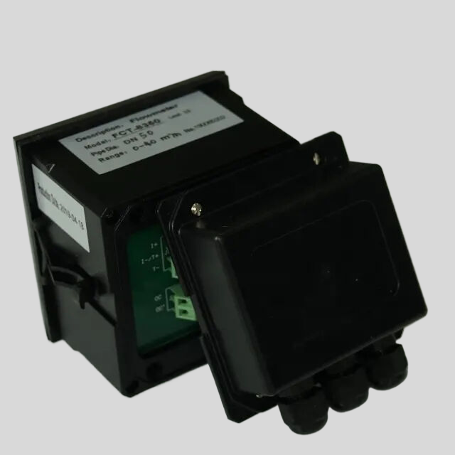
| FL-9900 High Precision Type Runner Flow Controller | ||
| Measuring range | Frequency | 0~2K Hz |
| Velocity of flow | 0.5~5 m/s | |
| Instantaneous flow | 0~2000 m³/h | |
| Cumulative flow | 0~9999 9999.999 m³ | |
| Applicable pipe diameter range | DN15~DN100;DN125~DN300 | |
| Resolution | 0.01 m³/h | |
| Refresh rate | 1s | |
| Accuracy class | Level 2.0 | |
| Repeatability | ±0.5% | |
| Sensor input | Radius:0~2K Hz | |
| Supply voltage:DC 24V(instrument internal supply) | ||
| The electronic unit automatically temperature compensates for errors | +0.5%FS; | |
| 4-20mA | Technical characteristics | Meter/transmitter dual mode (photoelectric isolation) |
| Loop resistance | 500Q(max),DC24V; | |
| Transmission accuracy | ±0.01mA | |
| Control port | Contact mode | Passive relay control output |
| Load capacity | Load current 5A (max) | |
| Function selection | Instantaneous flow upper/lower alarm | |
| Mains supply | Working voltage: DC24V 4V Power consumption :<; 3.OW | |
| Cable length | Factory configuration: 5m, can be agreed: (1~500) m | |
| Environmental requirement | Temperature: 0~50℃; Relative humidity: ≤85%RH | |
| Storage environment | Temperature: (-20~60) ℃; Humidity: 85%RH | |
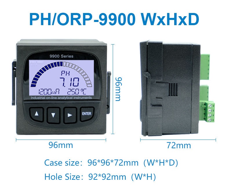
| Overall dimension | 96×96×72mm(height × width × depth) | |
| Opening size | 92×92mm | |
| Installation mode | Disc mounted, fast fixed | |
| Sensor | Body material | Body: Engineering plastic PP; Bearing :Zr02 high temperature zirconia |
| Flow rate range | 0.5~5 m/s | |
| Withstand pressure | ≤0.6MPa | |
| Supply voltage | lDC 24V | |
| Output pulse amplitude| | Vp≥8V | |
| Normal pipe diameter | DN15~DN100;DN125~DN600 | |
| Medium characteristic | Single-phase medium(0~60℃) | |
| Installation mode | Direct line insertion | |
To build a conductivity meter using Arduino, you will need a few key components. These include an Arduino board, a conductivity sensor, a resistor, and a breadboard. The Arduino board will serve as the brain of the conductivity meter, while the conductivity sensor will measure the electrical conductivity of the solution being tested. The resistor is used to create a voltage divider circuit, which is necessary for accurate conductivity measurements.
To begin building your conductivity meter, start by connecting the conductivity sensor to the Arduino board. The sensor typically has three pins: power, ground, and signal. Connect the power pin to the 5V pin on the Arduino, the ground pin to the GND pin, and the signal pin to one of the analog input pins (e.g., A0). Next, connect a resistor between the signal pin of the sensor and the ground pin to create the voltage divider circuit.
Once the hardware is set up, you can start writing the code for the Arduino. The code will read the analog input from the sensor, convert it to a conductivity value, and display the result on a connected display or serial monitor. You can also calibrate the conductivity meter by measuring the conductivity of a known solution and adjusting the code accordingly.
When writing the code, it is important to consider the range of conductivity values you expect to measure. Different solutions have different conductivity levels, so you may need to adjust the code to accommodate a wide range of values. Additionally, you can add features such as temperature compensation to improve the accuracy of your conductivity meter.
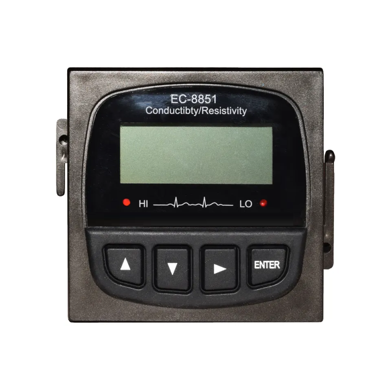
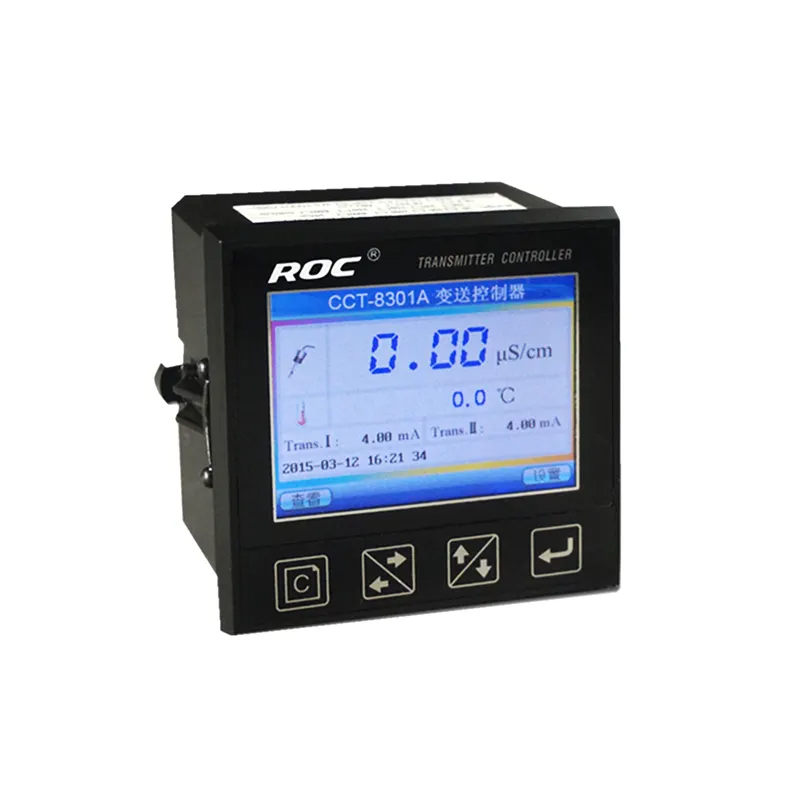
| ROC-2315 ro controller instruction (220V) | |||
| Model | ROC-2315 | ||
| Single detection | Dry Contact input | Raw water no water protection | |
| (six channels) | Low-pressure protection | ||
| High-pressure protection | |||
| Pure water tank high level | |||
| External control mode signal | |||
| Running reset | |||
| Control port | Dry Contact output | Raw water pump | SPST-NO low capacity : AC220V/3A Max ;AC110V/5A Max |
| (five channels) | Inlet valve | ||
| High pressure pump | |||
| Flush valve | |||
| Conductivity over-limit drainge valve | |||
| Measurement detection point | Product water conductivity and with Automatic Temperature compensation (0~50)℃ | ||
| Measurement range | Conductivity : 0.1~200μS/cm/1~2000μS/cm/10~999μS/cm (with different conductivity sensor ) | ||
| Product water temp. : 0~50℃ | |||
| Accuracy | 1.5 level | ||
| Power supply | AC220V (±10%) , 50/60Hz | ||
| Working environment | Temperature:(0~50)℃ ; | ||
| Relative Humidity :≤85%RH (no condensation ) | |||
| Dimension | 96×96×130mm( height ×width×depth) | ||
| Hole size | 91×91mm(height ×width) | ||
| Installation | Panel mounted ,fast installtion | ||
| Certification | CE | ||
Once the code is written and uploaded to the Arduino board, you can test your conductivity meter by dipping the sensor into a solution with known conductivity. The meter should display a value that corresponds to the conductivity of the solution. If the readings are inaccurate, you may need to recalibrate the meter or adjust the code further.
Building a conductivity meter using Arduino is a rewarding project that can help you learn more about electronics, programming, and the principles of conductivity measurement. By following the steps outlined above and experimenting with different solutions, you can create a reliable and cost-effective conductivity meter for your own use. Whether you are a hobbyist, student, or professional, building your own conductivity meter using Arduino is a valuable learning experience that can benefit you in various fields.

