Table of Contents
Proper Installation Techniques for Conductivity Probe Wiring Diagrams
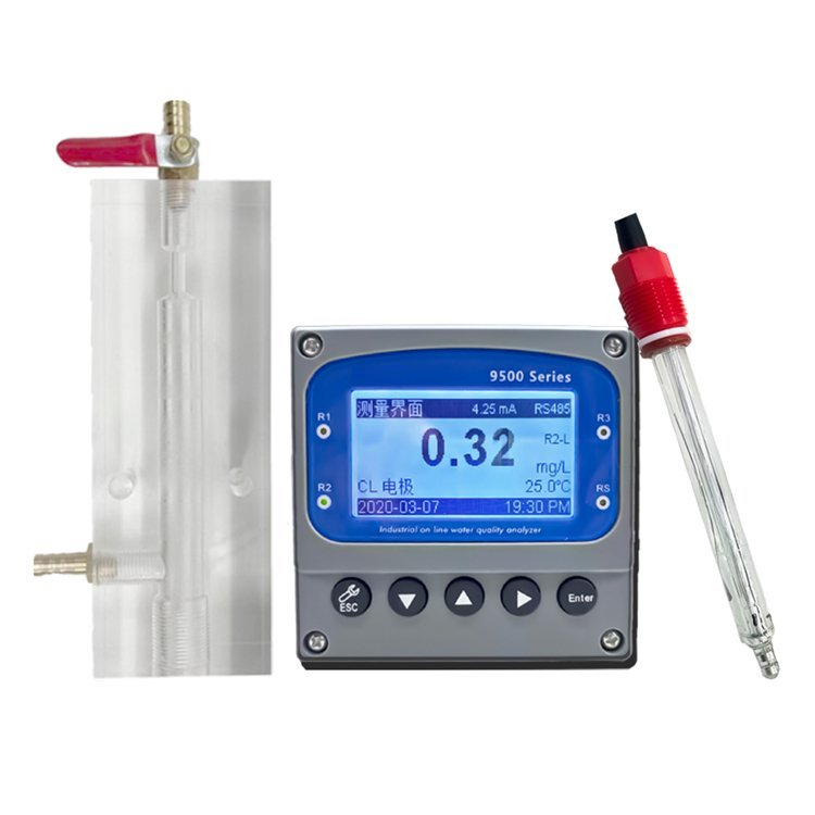
Conductivity probes are essential tools in various industries, including water treatment, food and beverage production, and pharmaceutical manufacturing. These probes measure the ability of a solution to conduct electricity, which is directly related to the concentration of ions present in the solution. Proper installation of conductivity probes is crucial to ensure accurate and reliable measurements. One key aspect of installation is the wiring diagram, which outlines how the probe should be connected to the control system.
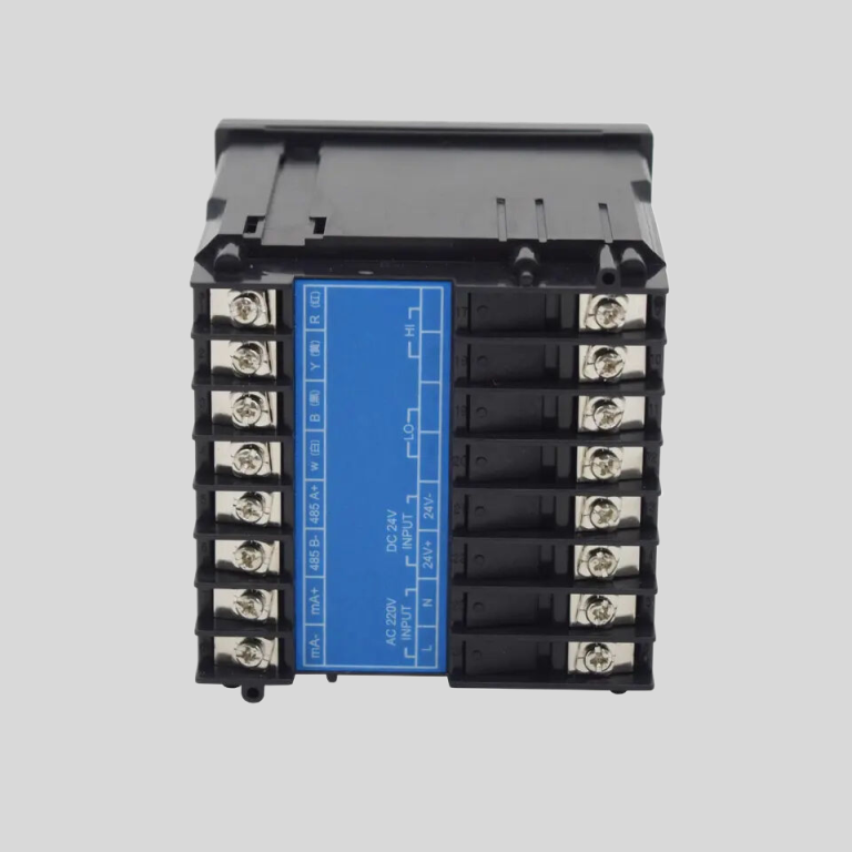
When it comes to wiring conductivity probes, following a wiring diagram is essential to ensure that the probe functions correctly. A typical wiring diagram for a conductivity probe includes connections for power, ground, signal output, and temperature compensation. It is important to carefully follow the wiring diagram provided by the manufacturer to avoid damaging the probe or obtaining inaccurate readings.
Before starting the installation process, it is important to gather all the necessary tools and materials, including the conductivity probe, wiring diagram, wire strippers, screwdrivers, and electrical tape. It is also crucial to ensure that the power to the system is turned off to prevent any accidents during the installation process.
The first step in wiring a conductivity probe is to connect the power and ground wires according to the wiring diagram. Typically, the power wire is connected to a power source, while the ground wire is connected to a ground terminal. It is important to double-check the connections to ensure that they are secure and properly insulated.
Next, the signal output wire from the conductivity probe should be connected to the input terminal on the control system. This wire carries the measurement signal from the probe to the control system, where it is processed and displayed. It is important to make sure that the signal output wire is connected to the correct terminal on the control system to avoid any errors in measurement.
In addition to the power, ground, and signal output connections, some conductivity probes also require a temperature compensation wire to be connected. This wire is used to compensate for changes in temperature that can affect the accuracy of the conductivity measurement. The temperature compensation wire should be connected according to the wiring diagram provided by the manufacturer.
Once all the wires are connected according to the wiring diagram, it is important to double-check the connections and ensure that they are secure. Any loose connections can lead to inaccurate readings or damage to the probe. It is also important to use electrical tape to insulate the connections and prevent any short circuits.
After the wiring is complete, it is important to power on the system and calibrate the conductivity probe according to the manufacturer’s instructions. Calibration ensures that the probe is providing accurate measurements and allows for any adjustments to be made if necessary.
| FL-9900 High Precision Type Runner Flow Controller | ||
| Measuring range | Frequency | 0~2K Hz |
| Velocity of flow | 0.5~5 m/s | |
| Instantaneous flow | 0~2000 m³/h | |
| Cumulative flow | 0~9999 9999.999 m³ | |
| Applicable pipe diameter range | DN15~DN100;DN125~DN300 | |
| Resolution | 0.01 m³/h | |
| Refresh rate | 1s | |
| Accuracy class | Level 2.0 | |
| Repeatability | ±0.5% | |
| Sensor input | Radius:0~2K Hz | |
| Supply voltage:DC 24V(instrument internal supply) | ||
| The electronic unit automatically temperature compensates for errors | +0.5%FS; | |
| 4-20mA | Technical characteristics | Meter/transmitter dual mode (photoelectric isolation) |
| Loop resistance | 500Q(max),DC24V; | |
| Transmission accuracy | ±0.01mA | |
| Control port | Contact mode | Passive relay control output |
| Load capacity | Load current 5A (max) | |
| Function selection | Instantaneous flow upper/lower alarm | |
| Mains supply | Working voltage: DC24V 4V Power consumption :<; 3.OW | |
| Cable length | Factory configuration: 5m, can be agreed: (1~500) m | |
| Environmental requirement | Temperature: 0~50℃; Relative humidity: ≤85%RH | |
| Storage environment | Temperature: (-20~60) ℃; Humidity: 85%RH | |
| Overall dimension | 96×96×72mm(height × width × depth) | |
| Opening size | 92×92mm | |
| Installation mode | Disc mounted, fast fixed | |
| Sensor | Body material | Body: Engineering plastic PP; Bearing :Zr02 high temperature zirconia |
| Flow rate range | 0.5~5 m/s | |
| Withstand pressure | ≤0.6MPa | |
| Supply voltage | lDC 24V | |
| Output pulse amplitude| | Vp≥8V | |
| Normal pipe diameter | DN15~DN100;DN125~DN600 | |
| Medium characteristic | Single-phase medium(0~60℃) | |
| Installation mode | Direct line insertion | |
In conclusion, proper installation of conductivity probes is essential to ensure accurate and reliable measurements. Following a wiring diagram is crucial to ensure that the probe is connected correctly to the control system. By carefully following the wiring diagram provided by the manufacturer and double-checking all connections, you can ensure that your conductivity probe functions correctly and provides accurate readings.
Troubleshooting Common Issues with Conductivity Probe Wiring Diagrams
Conductivity probes are essential tools in various industries, including water treatment, food processing, and pharmaceutical manufacturing. These probes measure the ability of a solution to conduct electricity, which is directly related to the concentration of ions present in the solution. Proper wiring of conductivity probes is crucial to ensure accurate readings and reliable performance. However, issues with wiring can lead to inaccurate readings, equipment malfunction, and costly downtime. In this article, we will discuss common issues with conductivity probe wiring diagrams and how to troubleshoot them.
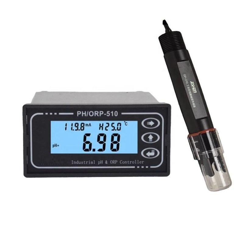
| Product name | pH/ORP-8500A transmitter controller | ||
| Measurement parameter | Measurement Range | Resolution ratio | Accuracy |
| pH | 0.00~14.00 | 0.01 | ±0.1 |
| ORP | (-1999~+1999)mV | 1mV | ±5mV(Electric meter) |
| Temperature | (0.0~100.0)℃ | 0.1℃ | ±0.5℃ |
| Temperature range of Tested solution | (0.0~100.0)℃ | ||
| Temperature component | NTC10K thermal element | ||
| (4~20)mA Current output | Channel No. | 2 channels | |
| Technical characteristics | Isolated, fully adjustable, reverse, | ||
| configurable, instrument / transmitting dual mode | |||
| Loop resistance | 400Ω(Max),DC 24V | ||
| Transmission accuracy | ±0.1mA | ||
| Control contact | Channel NO. | 3 Channels | |
| Electric contact | Semiconductor photoelectric switch | ||
| Programmable | Each channel can be programmed and point to (temperature, pH/ORP, time) | ||
| Technical characteristics | Presetting of normally open /normally closed state / pulse /PID regulation | ||
| Load capacity | 50mA(Max)AC/DC 30V | ||
| Data communication | MODBUS, RS485 standard protocol | ||
| Working power supply | DC 24V±4V | ||
| Overall power consumption | <5.5W | ||
| Working environment | Temperature: (0~50) ℃ | ||
| Relative humidity: ≤ 85%RH (non condensing) | |||
| Storage environment | Temperature: (-20~60) ℃ | ||
| Relative humidity: ≤ 85%RH (non condensing) | |||
| Protection level | IP65 (with back cover) | ||
| Shape size | 96mm×96 mm×94mm (H×W×D) | ||
| Opening size | 91mm×91mm(H×W) | ||
| Fixed mode | Panel mounting type quick fixed | ||
One common issue with conductivity probe wiring diagrams is incorrect wiring connections. It is essential to follow the manufacturer’s instructions carefully when connecting the probe to the control system. Each wire must be connected to the correct terminal to ensure proper signal transmission. If the wiring connections are incorrect, the probe may not function correctly, leading to inaccurate readings. To troubleshoot this issue, double-check the wiring connections against the wiring diagram provided by the manufacturer and make any necessary corrections.
Another common issue with conductivity probe wiring diagrams is damaged or frayed wires. Over time, wires can become damaged due to wear and tear, exposure to harsh chemicals, or improper handling. Damaged wires can lead to signal interference, poor conductivity, and unreliable readings. To troubleshoot this issue, inspect the wires for any signs of damage, such as fraying, cuts, or exposed conductors. If any damage is found, replace the damaged wires with new ones to ensure proper signal transmission.
Poor grounding is another common issue with conductivity probe wiring diagrams. Proper grounding is essential to ensure accurate readings and prevent electrical interference. If the probe is not properly grounded, it may pick up stray electrical signals, leading to inaccurate readings. To troubleshoot this issue, check the grounding connection of the probe and ensure that it is securely connected to a suitable grounding point. If the grounding connection is loose or damaged, repair or replace it to improve the probe’s performance.
Inadequate insulation is another common issue with conductivity probe wiring diagrams. Proper insulation is crucial to protect the wires from moisture, chemicals, and other environmental factors that can affect signal transmission. If the wires are not adequately insulated, they may short circuit, leading to equipment malfunction and safety hazards. To troubleshoot this issue, inspect the insulation of the wires and replace any damaged or worn-out insulation with new ones. Additionally, ensure that the wires are properly routed and secured to prevent damage to the insulation.
In conclusion, conductivity probe wiring diagrams are essential for ensuring accurate readings and reliable performance. Common issues with conductivity probe wiring diagrams, such as incorrect wiring connections, damaged wires, poor grounding, and inadequate insulation, can lead to inaccurate readings, equipment malfunction, and costly downtime. By following the manufacturer’s instructions, inspecting the wiring connections, and maintaining proper grounding and insulation, you can troubleshoot these issues and ensure the proper functioning of conductivity probes in your industrial processes.