How to Build an Arduino Water Monitoring System for Your Home
Water is a precious resource that is essential for life. With concerns about water scarcity and pollution on the rise, it is more important than ever to monitor and conserve water usage. One way to do this is by building an Arduino water monitoring system for your home. Arduino is an open-source electronics platform that allows you to create interactive projects. In this article, we will guide you through the process of building a simple water monitoring system using Arduino.
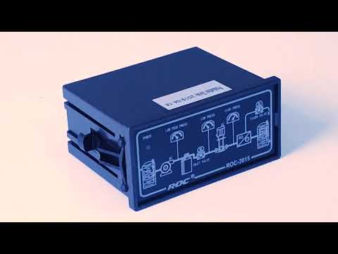
To build a water monitoring system, you will need a few key components. These include an Arduino board, a water flow sensor, a solenoid valve, and a display screen. The water flow sensor is used to measure the amount of water flowing through a pipe, while the solenoid valve can be used to control the flow of water. The display screen will show you real-time data on water usage.
The first step in building your water monitoring system is to connect the water flow sensor to the Arduino board. The water flow sensor has three pins: VCC, GND, and OUT. Connect the VCC pin to the 5V pin on the Arduino board, the GND pin to the GND pin, and the OUT pin to a digital pin, such as pin 2. Next, connect the solenoid valve to the Arduino board. The solenoid valve has two pins: VCC and GND. Connect the VCC pin to the 5V pin on the Arduino board and the GND pin to the GND pin.
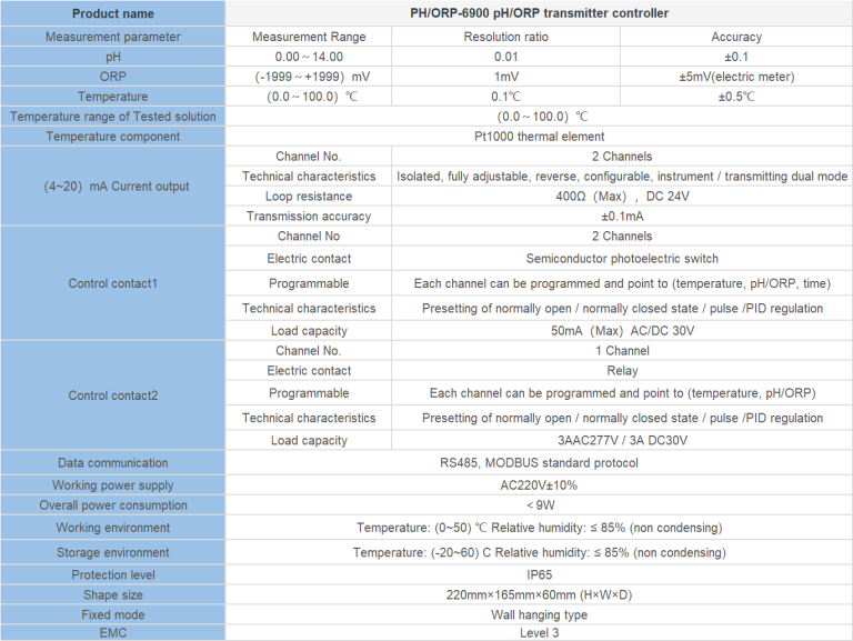
| Model | CIT-8800 Inductive Conductivity/Concentration Oline Controller |
| Concentration | 1.NaOH:(0~15)% or(25~50)%; 2.HNO3:(0~25)% or(36~82)%; 3.User-defined concentration curves |
| Conductivity | (500~2,000,000)uS/cm |
| TDS | (250~1,000,000)ppm |
| Temp. | (0~120)°C |
| Resolution | Conductivity: 0.01uS/cm; Concentration: 0.01%; TDS:0.01ppm, Temp.: 0.1℃ |
| Accuracy | Conductivity: (500~1000)uS/cm +/-10uS/cm; (1~2000)mS/cm+/-1.0% |
| TDS: 1.5 level, Temp.: +/-0.5℃ | |
| Temp. compensation | Range: (0~120)°C; element: Pt1000 |
| Communication port | RS485.Modbus RTU protocol |
| Analog output | Two channels isolated/ transportable (4-20)mA, Instrument / Transmitter for selection |
| Control Output | Triple channels semiconductor photoelectric switch, Programmable Switch, pulse and frequency |
| Working Environment | Temp.(0~50)℃; relative humidity <95%RH (non-condensing) |
| Storage Environment | Temp.(-20~60)℃;Relative Humidity ≤85%RH (none condensation) |
| Power Supply | DC 24V+15% |
| Protection Level | IP65 (with rear cover) |
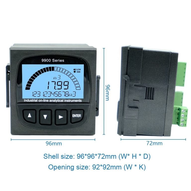
| Dimension | 96mmx96mmx94mm(HxWxD) |
| Hole Size | 9lmmx91mm(HxW) |
Once you have connected the components, you can start writing the code for your water monitoring system. The code will read the data from the water flow sensor and display it on the screen. It will also control the solenoid valve to regulate the flow of water. You can customize the code to set thresholds for water usage and receive alerts when these thresholds are exceeded.
After writing the code, upload it to the Arduino board and test your water monitoring system. You should see real-time data on water usage displayed on the screen. You can also test the solenoid valve by turning it on and off to control the flow of water. If everything is working correctly, you have successfully built a water monitoring system for your home.
| Model No. | CIT-8800 Inductive Conductivity / Concentration Online Controller | |
| Measurement range | Conductivity | 0.00μS/cm ~ 2000mS/cm |
| Concentration | 1.NaOH,(0-15)% or(25-50)%; | |
| 2.HNO3(note the Corrosion resistance of the sensor)(0-25)% or(36-82)%; | ||
| 3.User-defined concentration curves. | ||
| TDS | 0.00ppm~1000ppt | |
| Temp. | (0.0 ~ 120.0)℃ | |
| Resolution | Conductivity | 0.01μS/cm |
| Concentration | 0.01% | |
| TDS | 0.01ppm | |
| Temp. | 0.1℃ | |
| Accuracy | Conductivity | 0μS/cm ~1000μS/cm ±10μS/cm |
| 1 mS/cm~500 mS/cm ±1.0% | ||
| 500mS/cm~2000 mS/cm ±1.0% | ||
| TDS | 1.5 level | |
| Temp. | ±0.5℃ | |
| Temp. compensation | element | Pt1000 |
| range | (0.0~120.0)℃ linear compensation | |
| (4~20)mA Current output | channels | Double channels |
| features | Isolated, adjustable, reversible, 4-20MA output, instruments/ transmitter mode. | |
| Loop resistance | 400Ω(Max),DC 24V | |
| Resolution | ±0.1mA | |
| Control contact | Channels | Triple channels |
| Contact | Photoelectric relay output | |
| Programmable | Programmable ( temperature 、conductivity/concentration/TDS、timing)output | |
| Features | Could set temperature、conductivity/concentration/TDS、 timing NO/NC/ PID selection | |
| Resistance load | 50mA(Max),AC/DC 30V(Max) | |
| Data communication | RS485,MODBUS protocol | |
| Power supply | DC 24V±4V | |
| Consumption | <5.5W | |
| Working environment | Temperature:(0~50)℃ Relative Humidity:≤85%RH(non- condensing ) | |
| Storage | Temperature:(-20~60)℃ Relative Humidity:≤85%RH(non- condensing) | |
| Protection level | IP65(with rear cover) | |
| Outline dimension | 96mm×96 mm×94mm (H×W×D) | |
| Hole dimension | 91mm×91mm(H×W) | |
| Installation | Panel mounted , fast installation | |
In conclusion, building an Arduino water monitoring system is a simple and effective way to track and conserve water usage in your home. By monitoring water usage in real-time, you can identify areas where water is being wasted and take steps to reduce consumption. With the increasing importance of water conservation, a water monitoring system is a valuable tool for homeowners. So why not give it a try and start monitoring your water usage today?