Building Your Own Conductivity Probe for Water Quality Testing
Conductivity probes are essential tools for measuring the electrical conductivity of water, which can provide valuable insights into the quality and purity of the water. While there are many commercially available conductivity probes on the market, building your own DIY conductivity probe can be a cost-effective and rewarding project for those interested in water quality testing.
To build your own conductivity probe, you will need a few basic materials and tools. The most important component of the probe is the conductivity sensor, which is typically made of two electrodes that are immersed in the water being tested. These electrodes measure the electrical conductivity of the water, which is directly related to the concentration of dissolved ions in the water.
One of the simplest ways to create a conductivity sensor is to use two metal electrodes, such as stainless steel or platinum, that are connected to a circuit board. The circuit board can be connected to a microcontroller, such as an Arduino, which can then be used to measure the conductivity of the water and display the results on a screen or send them to a computer for further analysis.
| Model | FL-9900 Paddle Wheel flow meter |
| Range | Flow Speed:0.5-5 m/s |
| Instantaneous Flow:0-2000m3/h | |
| Accuracy | Level 2 |
| Temp. Comp. | Automatic temperature compensation |
| Oper. Temp. | Normal 0~60℃; High temp 0~100℃ |
| Sensor | Paddle Wheel Sensor |
| Pipeline | DN20-DN300 |
| Communication | 4-20mA output/RS485 |
| Control | Instantaneous Flow High/Low alarm |
| Load Current 5A(Max) | |
| Power | 220V/110V/24V |
| Working Environment | Ambient temperature:0~50℃ |
| Relative humidity≤85% | |
| Dimensions | 96×96×72mm(H×W×L) |
| Hole Size | 92×92mm(H×W) |
| Installation Mode | Embedded |
In addition to the conductivity sensor, you will also need a housing for the probe to protect it from water damage and ensure accurate measurements. This can be as simple as a plastic tube or container that is sealed to prevent water from entering the probe.
Once you have assembled your DIY conductivity probe, you can begin using it to test the conductivity of various water sources, such as tap water, river water, or even water from a fish tank. By comparing the conductivity readings from different sources, you can gain valuable insights into the quality of the water and identify any potential contaminants or pollutants that may be present.
In addition to measuring conductivity, DIY conductivity probes can also be used to monitor changes in water quality over time. By taking regular measurements and tracking the results, you can identify trends and patterns that may indicate changes in the water’s composition or contamination levels.
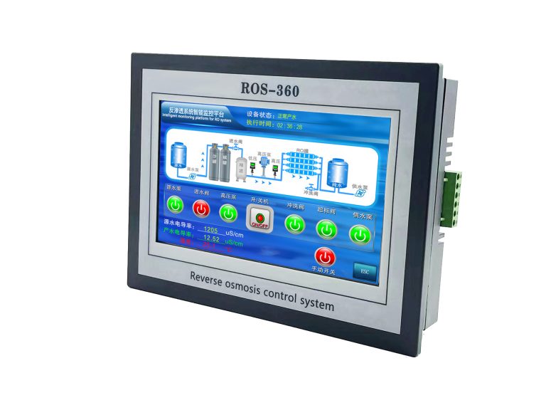
| ROS-8600 RO Program Control HMI Platform | ||
| Model | ROS-8600 Single Stage | ROS-8600 Double Stage |
| Measuring range | Source water0~2000uS/cm | Source water0~2000uS/cm |
| First level effluent 0~200uS/cm | First level effluent 0~200uS/cm | |
| secondary effluent 0~20uS/cm | secondary effluent 0~20uS/cm | |
| Pressure sensor(optional) | Membrane pre/post pressure | Primary/ secondary membrane front/rear pressure |
| ph sensor(optional) | —- | 0~14.00pH |
| Signal collection | 1.Raw water low pressure | 1.Raw water low pressure |
| 2.Primary booster pump inlet low pressure | 2.Primary booster pump inlet low pressure | |
| 3.Primary booster pump outlet high pressure | 3.Primary booster pump outlet high pressure | |
| 4.High liquid level of Level 1 tank | 4.High liquid level of Level 1 tank | |
| 5.Low liquid level of Level 1 tank | 5.Low liquid level of Level 1 tank | |
| 6.Preprocessing signal | 6.2nd booster pump outlet high pressure | |
| 7.Input standby ports x2 | 7.High liquid level of Level 2 tank | |
| 8.Low liquid level of Level 2 tank | ||
| 9.Preprocessing signal | ||
| 10.Input standby ports x2 | ||
| Output control | 1.Water inlet valve | 1.Water inlet valve |
| 2.Source water pump | 2.Source water pump | |
| 3.Primary booster pump | 3.Primary booster pump | |
| 4.Primary flush valve | 4.Primary flush valve | |
| 5.Primary dosing pump | 5.Primary dosing pump | |
| 6.Primary water over standard discharge valve | 6.Primary water over standard discharge valve | |
| 7.Alarm output node | 7.Secondary booster pump | |
| 8.Manual standby pump | 8.Secondary flush valve | |
| 9.Secondary dosing pump | 9.Secondary dosing pump | |
| Output standby port x2 | 10.Secondary water over standard discharge valve | |
| 11.Alarm output node | ||
| 12.Manual standby pump | ||
| Output standby port x2 | ||
| The main function | 1.Correction of electrode constant | 1.Correction of electrode constant |
| 2.Overrun alarm setting | 2.Overrun alarm setting | |
| 3.All working mode time can be set | 3.All working mode time can be set | |
| 4.High and low pressure flushing mode setting | 4.High and low pressure flushing mode setting | |
| 5.The low pressure pump is opened when preprocessing | 5.The low pressure pump is opened when preprocessing | |
| 6.Manual/automatic can be chosen when boot up | 6.Manual/automatic can be chosen when boot up | |
| 7.Manual debugging mode | 7.Manual debugging mode | |
| 8.Alarm if communication interruption | 8.Alarm if communication interruption | |
| 9. Urging payment settings | 9. Urging payment settings | |
| 10. Company name,website can be customized | 10. Company name,website can be customized | |
| Power supply | DC24V±10% | DC24V±10% |
| Expansion interface | 1.Reserved relay output | 1.Reserved relay output |
| 2.RS485 communication | 2.RS485 communication | |
| 3.Reserved IO port, analog module | 3.Reserved IO port, analog module | |
| 4.Mobile/computer/touch screen synchronous display | 4.Mobile/computer/touch screen synchronous display | |
| Relative humidity | ≦85% | ≤85% |
| Environment temperature | 0~50℃ | 0~50℃ |
| Touch screen size | 163x226x80mm (H x W x D) | 163x226x80mm (H x W x D) |
| Hole Size | 7 inch:215*152mm(wide*high) | 215*152mm(wide*high) |
| Controller size | 180*99(long*wide) | 180*99(long*wide) |
| Transmitter size | 92*125(long*wide) | 92*125(long*wide) |
| Installation method | Touch screen:panel embedded; Controller: plane fixed | Touch screen:panel embedded; Controller: plane fixed |

Overall, building your own conductivity probe can be a fun and educational project that allows you to gain a better understanding of water quality testing and monitoring. With a few basic materials and some basic electronics knowledge, you can create a reliable and accurate conductivity probe that can be used for a variety of water testing applications.
Whether you are a hobbyist looking to explore the world of water quality testing or a professional seeking a cost-effective solution for monitoring water quality, building your own DIY conductivity probe can be a rewarding and valuable experience. By following these simple steps and guidelines, you can create a reliable and accurate conductivity probe that will help you better understand and protect the quality of the water around you.