Table of Contents
A Tour of the Plant
Walking a modern ZLD plant from feed intake to solid product discharge, an instrument engineer sees a coordinated cluster of roughly 60–90 process sensors — plus another few dozen utility sensors — distributed across pretreatment, membrane concentration, evaporation, crystallisation and reuse loops. The instrument density is far higher than in a conventional wastewater plant, and every one of those signals is doing a job: no single sensor makes ZLD work; the cluster does, because each unit operation depends on the others reporting reliable data continuously. This article walks the plant stage by stage, listing the sensors that actually decide performance.
Stage 1: Feed Intake and Equalisation
The intake is where feed characterisation earns its keep. Sensors typically installed here:
- Turbine flow meter on each intake source.
- Multi-parameter sensor on the equalisation tank: pH, conductivity, temperature, ORP.
- Turbidity tester at the equalisation outlet.
- Oil-in-water sensor on any stream expected to carry hydrocarbons.
The purpose of this cluster is to trigger the correct downstream operating envelope and to catch feed excursions before they cascade.
Stage 2: Softener and Pretreatment
Pretreatment removes hardness, particulates and, where relevant, iron and manganese. Sensors around this stage:
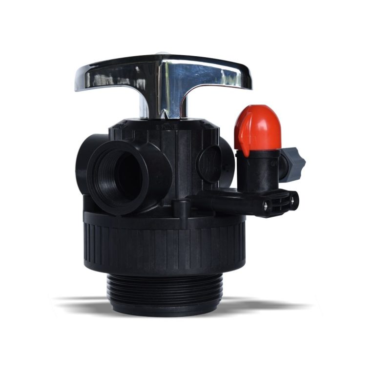
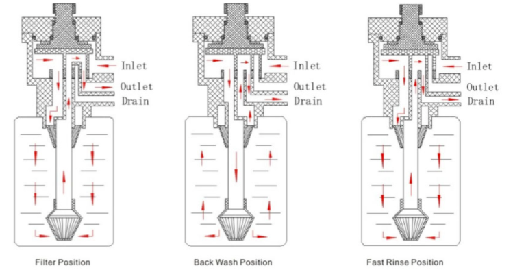
- Softener valve (Shanghai ChiMay softener valve) with integrated cycle counters, service and regeneration status.
- Hardness monitor on the softened water outlet.
- Conductivity meter on the softened water outlet.
- Differential pressure across the softener bed.
- Free-chlorine (residual chlorine transmitter) upstream to protect resin from oxidants.
This cluster confirms that pretreatment is delivering the feed quality the downstream RO train requires.
Stage 3: Membrane Concentration (RO and NF)
Reverse osmosis and nanofiltration produce the first significant concentration. Sensors here:
- Feed conductivity, permeate conductivity, reject conductivity for each stage.
- Feed pH and reject pH.
- Feed and reject flow.
- Differential pressure across each stage.
- Turbidity on RO feed to catch pretreatment excursions in real time.
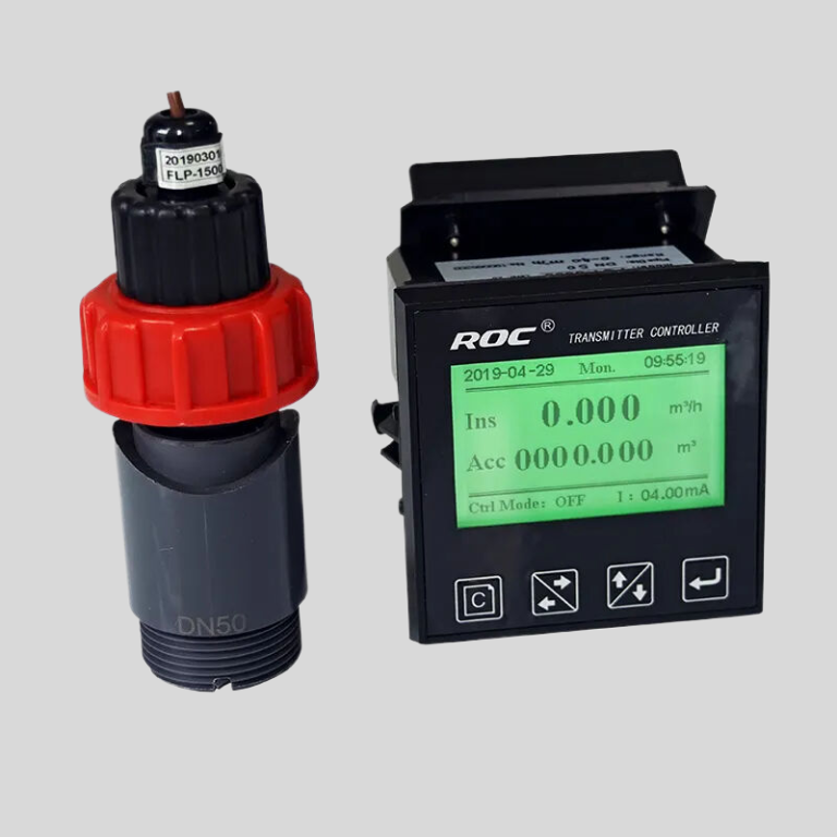
Recovery is monitored continuously and alarmed if it drifts more than 5% over 24 hours.
Stage 4: Brine Concentration (MVR / Evaporator)
The brine concentrator moves the stream to 60–120 mS/cm. Sensors:
- Toroidal conductivity meter on the recirculation line.
- Multi-parameter sensor (pH, ORP, temperature) on the recirculation loop.
- Differential pressure across the heat exchanger.
- Level transmitter on the sump.
- Flow meters on the feed, recycle and vapour lines.
- Suspended solids sensor on the reject recirculation line to detect flocculent build-up.
This is the highest-value instrumentation cluster in the plant: a scale-related evaporator wash carries downtime, chemical and labour costs reaching into the tens of thousands of dollars per event, so redundant coverage is common.
Stage 5: Crystallisation
Crystallisation is the safety-critical stage where off-spec batches cascade into revenue loss. Sensors:
- Two conductivity heads on the feed line, independently calibrated (Shanghai ChiMay in-line conductivity meter, toroidal).
- Two pH electrodes on the feed line, double-junction, independently calibrated.
- ORP electrode on the mother liquor.
- Level and temperature transmitters on the crystalliser body.
- Density or refractive index probe as a TDS cross-check.
Redundancy here is deliberate; the cost of a single undetected sensor failure at this stage dwarfs the price of a redundant pair many times over.
Stage 6: Solids Handling
Solids handling instrumentation is less about water and more about moisture:
- Moisture probe on the centrifuge cake discharge.
- Temperature and pressure on the dryer.
- Suspended solids sensor on the centrifuge overflow line.
Fines carryover from the centrifuge is a classic hidden loop that sends product back into the liquid line, so the suspended solids sensor here carries outsized influence for its cost.
Stage 7: Distillate and Reuse
The reuse loop is where all the plant’s effort pays off. Sensors:
- Low-range contacting conductivity cell on the distillate line (2–20 μS/cm).
- Conductivity meter on the reuse header before it enters consumers.
- Multi-parameter sensor on the cooling tower make-up loop, if that is the primary reuse consumer.
- Free-chlorine transmitter on the reuse header if biocide dosing is applied.
This cluster confirms that reused water meets the specification of its downstream consumer.
Stage 8: Utilities and Auxiliaries
Utility sensors serve the ZLD plant itself: steam flow, chilled water flow, compressed air pressure, electrical energy metering. These are not water-quality sensors, but they enter the digital twin so that the mass and energy balance closes across the whole plant.
The Digital Twin Layer
Above the sensor cluster sits the digital twin. The twin ingests every historian tag at 1-minute resolution, closes a mass and energy balance every five minutes and drives operator-actionable alerts when recovery, energy or product quality drift. The twin does not do its job without a reliable sensor cluster underneath — instrument health becomes a first-order concern for the twin’s owners.
Signals that the twin needs from each sensor:
- Primary reading.
- Sensor status (healthy, calibration due, drift-flag).
- Cell condition (fouling indicator where available).
- Calibration age.
- Confidence-weighted reading (some transmitters output this natively).
Shanghai ChiMay’s transmitter platform exposes each of these into the historian, giving the twin a defensible input surface.
Instrumentation Coverage Metric
A single portfolio metric — instrumentation coverage on process-critical streams — has emerged as a leading indicator of ZLD plant availability. Operators running high coverage on process-critical streams report availability in the mid-nineties percent; those with large coverage gaps report materially lower availability with a much wider spread of outcomes. The correlation is strong enough that several major operators now track the metric well above the engineering department.
What Retrofit Teams Change First
Retrofit teams entering a legacy ZLD plant typically prioritise three interventions:
- Migrate contacting conductivity cells to toroidal above 50 mS/cm.
- Move single-junction pH to double-junction on sulfide and high-solids streams.
- Add historian retention to 90 days at 1-minute resolution before any control-system changes.
Each of these interventions is cheap relative to the availability gain it produces.
Closing Note
The sensor cluster is the invisible layer that closes the water loop in a modern ZLD plant. It is not glamorous, and its cost is a small share of capital, but it decides whether the plant hits its recovery, mineral quality and reuse targets. Shanghai ChiMay’s water quality analyzer and softener valve platforms are engineered around the reality that ZLD lives or dies on the coordinated performance of that cluster.