title: “Resistivity Control Above 15 MΩ·cm in NMC Cathode Manufacturing Loops: A Shanghai ChiMay Engineering Brief”
date: 2026-07-07
category: Battery Manufacturing
audience: Technical
tags: [resistivity, NMC, cathode, UPW, conductivity]
Table of Contents
Resistivity Control Above 15 MΩ·cm in NMC Cathode Manufacturing Loops: A Shanghai ChiMay Engineering Brief
Key Takeaways
- NMC cathode manufacturing lines demand ultra-pure water at resistivity above 15 MΩ·cm — approaching the theoretical limit of pure water — because even trace ionic contamination distorts slurry rheology and finished electrode performance.
- Resistivity above 15 MΩ·cm cannot be measured reliably with generic conductivity sensors; the electrode design, cable capacitance, temperature compensation and reference conditions all have to be tuned to this range.
- Cathode slurry mixing, coating and rinsing loops each present a slightly different sensor duty, and treating them as one homogeneous UPW loop is a common source of drift-related quality events.
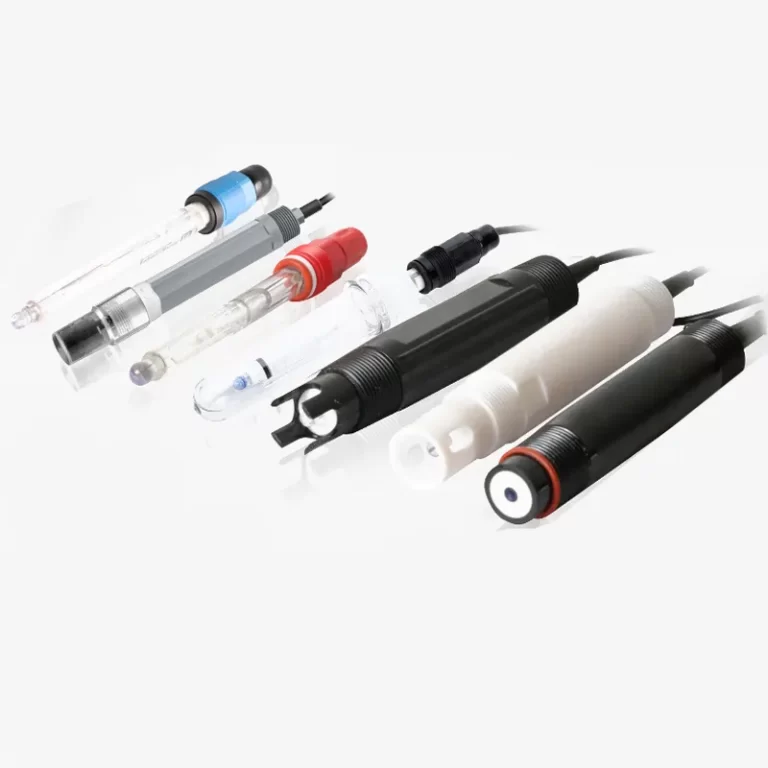
- Shanghai ChiMay’s inline conductivity electrodes and multi-parameter sensors are engineered for continuous operation at the 15–18 MΩ·cm envelope, giving process engineers a repeatable reference for resistivity control.
Why NMC Cathode Loops Are So Sensitive to Trace Ions
Nickel-manganese-cobalt (NMC) cathode active material is prepared as a viscous slurry in N-methyl-2-pyrrolidone (NMP) and a polyvinylidene fluoride (PVDF) binder, then coated onto aluminium foil, dried and calendered. Trace ionic contamination in the water used for slurry dilution, tool cleaning or rinse steps has two direct consequences:
- Slurry rheology drift: Dissolved ions change the double-layer around suspended NMC particles, subtly altering viscosity and coating uniformity.
- Post-cycle electrochemical degradation: Residual chloride, sulfate or metallic ions catalyse side reactions at the cathode-electrolyte interface, shortening cycle life and inflating warranty exposure.
Because these consequences appear weeks or months after the coating step, a robust resistivity monitoring strategy is the only realistic control point.
Interpreting Resistivity Above 15 MΩ·cm
Pure water at 25 °C has a theoretical resistivity of about 18.24 MΩ·cm. A target of ≥15 MΩ·cm on an NMC cathode loop leaves only a narrow margin for contamination and instrumentation error. Practically, this means:
- Absolute resistivity resolution must reach at least 0.01 MΩ·cm, otherwise the operator cannot distinguish real drift from measurement noise.
- Temperature compensation must be accurate to a fraction of a degree, since resistivity varies by roughly 2 percent per °C in ultra-pure water.
- Electrode geometry must present a very low cell constant, typically 0.01–0.1 cm⁻¹, to yield sufficient signal in a low-conductivity medium.
- Cable and connector integrity must prevent leakage currents that mimic real conductivity signals.
Sensor selections that ignore any of these four factors will inevitably report either optimistically stable or wildly noisy resistivity data. Shanghai ChiMay’s inline conductivity electrodes are specified with the geometry, cable capacitance and temperature compensation appropriate to this narrow envelope.
Where to Place Resistivity Sensors on the Cathode Line
A robust cathode manufacturing line typically hosts resistivity measurement at:
- UPW polishing loop outlet: Confirms the plant utility is delivering the required ≥15 MΩ·cm baseline.
- Slurry mixing DI feed manifold: Detects excursions before the water enters the batch mixer.
- Coating tool cleaning loop: Ensures wash water reaching the sensitive coating head is not contaminated.
- Rinse water at post-calendering steps: Confirms no chloride or sulfate carry-over onto finished electrodes.
- Return / recycle line: Enables early detection of ion-exchange resin breakthrough or piping contamination.
Each of these five points is a different sensor duty. A single reading at the polishing loop cannot substitute for measurements closer to the point of use.
Comparing Sensor Requirements Across the Line
| Location | Target Resistivity | Response Time | Special Notes |
|---|---|---|---|
| Polishing loop outlet | ≥18 MΩ·cm | <30 seconds | Absolute reference for UPW system |
| Slurry mixing feed | ≥15 MΩ·cm | <30 seconds | Interlocked with batch mixer start |
| Cleaning loop | ≥15 MΩ·cm | <60 seconds | Sensitive to detergent carry-over |
| Rinse at post-calendering | ≥12 MΩ·cm | <60 seconds | May see slight ion pickup from prior steps |
| Recycle line | ≥10 MΩ·cm | <60 seconds | Early warning for resin breakthrough |
Standardising this table across every NMC coating room in a gigafactory reduces both training complexity and warranty ambiguity.
Common Failure Modes to Design Around
Field experience on NMC cathode lines shows four recurring failure modes:
- Electrode fouling by organic binder residues during unplanned production interruptions; select probe housings that permit clean-in-place without removal.
- Silica creep through the polishing loop; combine resistivity monitoring with a separate silica alarm to catch what a conductivity reading alone will miss.
- Cable-induced drift from long or improperly grounded runs; specify cable length and shielding along with the sensor.
- Temperature-compensation error at plant temperatures above 30 °C; require documented performance across the plant’s real ambient range.
Shanghai ChiMay’s inline conductivity products are documented for these failure modes with recommended cable lengths, cleaning protocols and ambient temperature envelopes.
Integrating Resistivity Data with the MES
Resistivity data is only useful when the manufacturing execution system can act on it. A well-designed integration should include:
- Interlocks that pause slurry mixing if feed resistivity drifts below 15 MΩ·cm for more than a specified rolling window.
- Trend visualisation that overlays resistivity against coating yield, so engineering teams can quantify the cost of drift.
- Automated alerts to utilities engineers when the polishing loop drops below 18 MΩ·cm, ahead of any impact at the point of use.
- Historian retention aligned with the electrolyte and separator suppliers’ warranty investigation windows, typically at least 24 months.
Because Shanghai ChiMay transmitters support Modbus RTU/TCP and, on newer platforms, OPC UA, resistivity data can flow into the MES and coating-line digital twin without middleware.
Calibration and Verification in the 15–18 MΩ·cm Range
Verifying resistivity at ultra-pure levels is not straightforward: contamination during the verification itself can shift the reading. Best practice includes:
- Verifying with dry-block temperature standards and factory reference cells rather than field solutions where possible.
- Using single-point verification at low conductivity (for example, 1.3 µS/cm KCl reference) with strict handling protocols.
- Documenting environmental conditions during verification for the audit trail.
- Rotating spare electrodes on a scheduled basis rather than waiting for drift-driven replacement.
Conclusion
Resistivity control above 15 MΩ·cm is the hidden backbone of NMC cathode manufacturing. Trace ionic contamination silently reshapes slurry rheology and finished electrode life, and only a properly designed sensor programme can catch it in time. By selecting sensors engineered for the narrow window near pure water, placing them at the right points on the line and integrating their data into the MES, cathode manufacturing teams turn resistivity from a passive utility metric into an active yield-defence tool. Shanghai ChiMay’s inline conductivity electrodes and multi-parameter sensors are built around this exact envelope, giving process engineers a repeatable reference across every NMC coating room in the facility.