How to Install and Calibrate the YF-S201 Flow Sensor for Accurate Measurements
Flow sensors are essential devices used in various industries to measure the flow rate of liquids. One popular flow sensor is the YF-S201, known for its accuracy and reliability. In this article, we will discuss how to properly install and calibrate the YF-S201 flow sensor to ensure accurate measurements.
Before installing the YF-S201 flow sensor, it is important to gather all the necessary tools and materials. You will need a power source, a microcontroller or data logger, connecting wires, and a suitable mounting location for the sensor. Once you have everything ready, you can begin the installation process.
The first step in installing the YF-S201 flow sensor is to determine the direction of flow. The sensor should be installed in such a way that the liquid flows in the direction indicated by the arrow on the sensor body. This will ensure that the sensor can accurately measure the flow rate of the liquid passing through it.
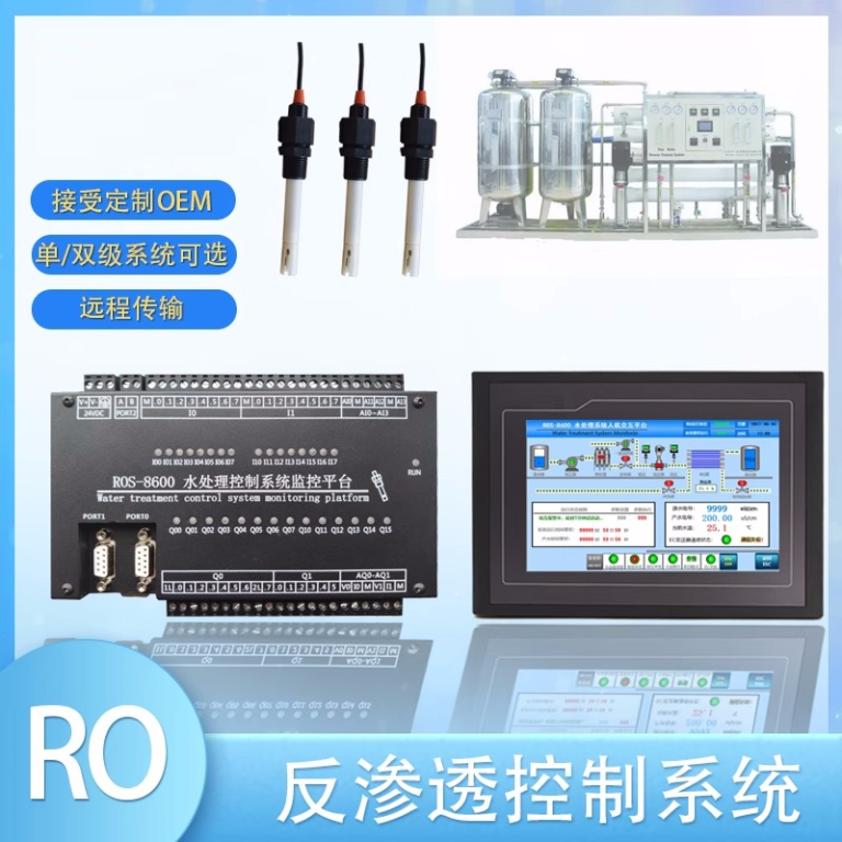
| ROS-8600 RO Program Control HMI Platform | ||
| Model | ROS-8600 Single Stage | ROS-8600 Double Stage |
| Measuring range | Source water0~2000uS/cm | Source water0~2000uS/cm |
| \u3000 | First level effluent 0~200uS/cm | First level effluent 0~200uS/cm |
| \u3000 | secondary effluent 0~20uS/cm | secondary effluent 0~20uS/cm |
| Pressure sensor(optional) | Membrane pre/post pressure | Primary/ secondary membrane front/rear pressure |
| ph sensor(optional) | —- | 0~14.00pH |
| Signal collection | 1.Raw water low pressure | 1.Raw water low pressure |
| \u3000 | 2.Primary booster pump inlet low pressure | 2.Primary booster pump inlet low pressure |
| \u3000 | 3.Primary booster pump outlet high pressure | 3.Primary booster pump outlet high pressure |
| \u3000 | 4.High liquid level of Level 1 tank | 4.High liquid level of Level 1 tank |
| \u3000 | 5.Low liquid level of Level 1 tank | 5.Low liquid level of Level 1 tank |
| \u3000 | 6.Preprocessing signal\u00a0 | 6.2nd booster pump outlet high pressure |
| \u3000 | 7.Input standby ports x2 | 7.High liquid level of Level 2 tank |
| \u3000 | \u3000 | 8.Low liquid level of Level 2 tank |
| \u3000 | \u3000 | 9.Preprocessing signal |
| \u3000 | \u3000 | 10.Input standby ports x2 |
| Output control | 1.Water inlet valve | 1.Water inlet valve |
| \u3000 | 2.Source water pump | 2.Source water pump |
| \u3000 | 3.Primary booster pump | 3.Primary booster pump |
| \u3000 | 4.Primary flush valve | 4.Primary flush valve |
| \u3000 | 5.Primary dosing pump | 5.Primary dosing pump |
| \u3000 | 6.Primary water over standard discharge valve | 6.Primary water over standard discharge valve |
| \u3000 | 7.Alarm output node | 7.Secondary booster pump |
| \u3000 | 8.Manual standby pump | 8.Secondary flush valve |
| \u3000 | 9.Secondary dosing pump | 9.Secondary dosing pump |
| \u3000 | Output standby port x2 | 10.Secondary water over standard discharge valve |
| \u3000 | \u3000 | 11.Alarm output node |
| \u3000 | \u3000 | 12.Manual standby pump |
| \u3000 | \u3000 | Output standby port x2 |
| The main function | 1.Correction of electrode constant | 1.Correction of electrode constant |
| \u3000 | 2.Overrun alarm setting | 2.Overrun alarm setting |
| \u3000 | 3.All working mode time can be set | 3.All working mode time can be set |
| \u3000 | 4.High and low pressure flushing mode setting | 4.High and low pressure flushing mode setting |
| \u3000 | 5.The low pressure pump is opened when preprocessing | 5.The low pressure pump is opened when preprocessing |
| \u3000 | 6.Manual/automatic can be chosen when boot up | 6.Manual/automatic can be chosen when boot up |
| \u3000 | 7.Manual debugging mode | 7.Manual debugging mode |
| \u3000 | 8.Alarm if communication interruption | 8.Alarm if communication interruption |
| \u3000 | 9. Urging payment settings | 9. Urging payment settings |
| \u3000 | 10. Company name,website can be customized | 10. Company name,website can be customized |
| Power supply | DC24V\u00b110% | DC24V\u00b110% |
| Expansion interface | 1.Reserved relay output | 1.Reserved relay output |
| \u3000 | 2.RS485 communication | 2.RS485 communication |
| \u3000 | 3.Reserved IO port, analog module | 3.Reserved IO port, analog module |
| \u3000 | 4.Mobile/computer/touch screen synchronous display\u00a0 | 4.Mobile/computer/touch screen synchronous display\u00a0 |
| Relative humidity | \u226685% | \u226485% |
| Environment temperature | 0~50\u2103 | 0~50\u2103 |
| Touch screen size | 163x226x80mm (H x W x D) | 163x226x80mm (H x W x D) |
| Hole Size | 7 inch:215*152mm(wide*high) | 215*152mm(wide*high) |
| Controller size | 180*99(long*wide) | 180*99(long*wide) |
| Transmitter size | 92*125(long*wide) | 92*125(long*wide) |
| Installation method | Touch screen:panel embedded; Controller: plane fixed | Touch screen:panel embedded; Controller: plane fixed |
Next, you will need to connect the sensor to the power source and the microcontroller or data logger. The YF-S201 flow sensor typically has three wires \u2013 red for power, black for ground, and yellow for signal output. Make sure to connect the wires correctly to avoid any damage to the sensor or the connected devices.
Once the sensor is properly connected, you can proceed to calibrate it for accurate measurements. Calibration is essential to ensure that the sensor provides reliable and consistent readings. To calibrate the YF-S201 flow sensor, you will need a known flow rate of the liquid passing through the sensor.
Start by setting the known flow rate on the microcontroller or data logger. Then, allow the liquid to flow through the sensor at the known rate while monitoring the output signal from the sensor. Adjust the calibration settings on the microcontroller or data logger until the output signal matches the known flow rate.
It is important to note that calibration may need to be done periodically to account for any changes in the sensor’s performance over time. Regular calibration will help maintain the accuracy of the sensor and ensure that it continues to provide reliable measurements.

In addition to calibration, proper maintenance of the YF-S201 flow sensor is also important to ensure its longevity and accuracy. Regular cleaning of the sensor and the surrounding area will help prevent any buildup of debris or contaminants that could affect its performance.
In conclusion, the YF-S201 flow sensor is a reliable and accurate device for measuring the flow rate of liquids. By following the proper installation and calibration procedures outlined in this article, you can ensure that the sensor provides accurate measurements for your application. Remember to calibrate the sensor regularly and maintain it properly to maximize its performance and longevity.

