“Measuring electrical conductivity for accurate results.”
Understanding the Principle of Conductivity Measurement in a conductivity meter
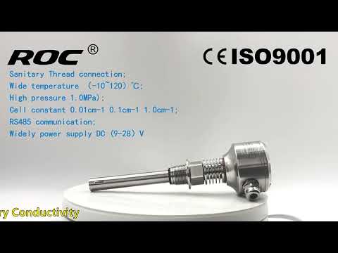
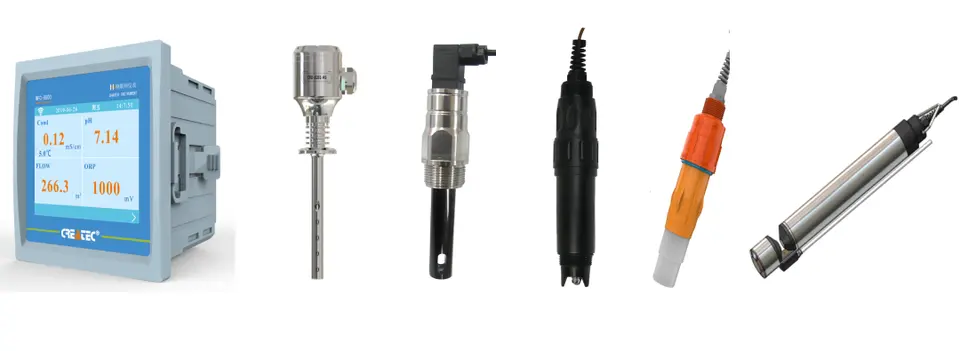
Conductivity meters are widely used in various industries to measure the ability of a solution to conduct electricity. This measurement is crucial in determining the purity of water, monitoring chemical processes, and ensuring the quality of products. But how exactly does a conductivity meter work? To understand this, we need to delve into the principle on which conductivity meters operate.
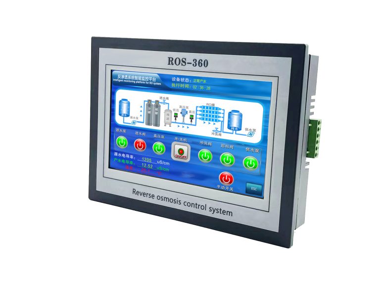
| ROS-360 Water Treatment RO Programmer Controller | ||
| Model | ROS-360 Single Stage | ROS-360 Double Stage |
| Measuring range | Source water0~2000uS/cm | Source water0~2000uS/cm |
| First level effluent 0~1000uS/cm | First level effluent 0~1000uS/cm | |
| secondary effluent 0~100uS/cm | secondary effluent 0~100uS/cm | |
| Pressure sensor(optional) | Membrane pre/post pressure | Primary/ secondary membrane front/rear pressure |
| Flow Sensor(optional) | 2 channels (Inlet/outlet flow rate) | 3 channels (source water, primary flow,secondary flow) |
| IO input | 1.Raw water low pressure | 1.Raw water low pressure |
| 2.Primary booster pump inlet low pressure | 2.Primary booster pump inlet low pressure | |
| 3.Primary booster pump outlet high pressure | 3.Primary booster pump outlet high pressure | |
| 4.High liquid level of Level 1 tank | 4.High liquid level of Level 1 tank | |
| 5.Low liquid level of Level 1 tank | 5.Low liquid level of Level 1 tank | |
| 6.Preprocessing signal | 6.2nd booster pump outlet high pressure | |
| 7.High liquid level of Level 2 tank | ||
| 8.Preprocessing signal | ||
| Relay output (passive) | 1.Water inlet valve | 1.Water inlet valve |
| 2.Source water pump | 2.Source water pump | |
| 3.Booster pump | 3.Primary booster pump | |
| 4.Flush valve | 4.Primary flush valve | |
| 5.Water over standard discharge valve | 5.Primary water over standard discharge valve | |
| 6.Alarm output node | 6.Secondary booster pump | |
| 7.Manual standby pump | 7.Secondary flush valve | |
| 8.Secondary water over standard discharge valve | ||
| 9.Alarm output node | ||
| 10.Manual standby pump | ||
| The main function | 1.Correction of electrode constant | 1.Correction of electrode constant |
| 2.TDS alarm setting | 2.TDS alarm setting | |
| 3.All working mode time can be set | 3.All working mode time can be set | |
| 4.High and low pressure flushing mode setting | 4.High and low pressure flushing mode setting | |
| 5.Manual/automatic can be chosen when boot up | 5.Manual/automatic can be chosen when boot up | |
| 6.Manual debugging mode | 6.Manual debugging mode | |
| 7.Spare parts time management | 7.Spare parts time management | |
| Expansion interface | 1.Reserved relay output | 1.Reserved relay output |
| 2.RS485 communication | 2.RS485 communication | |
| Power supply | DC24V±10% | DC24V±10% |
| Relative humidity | ≦85% | ≤85% |
| Environment temperature | 0~50℃ | 0~50℃ |
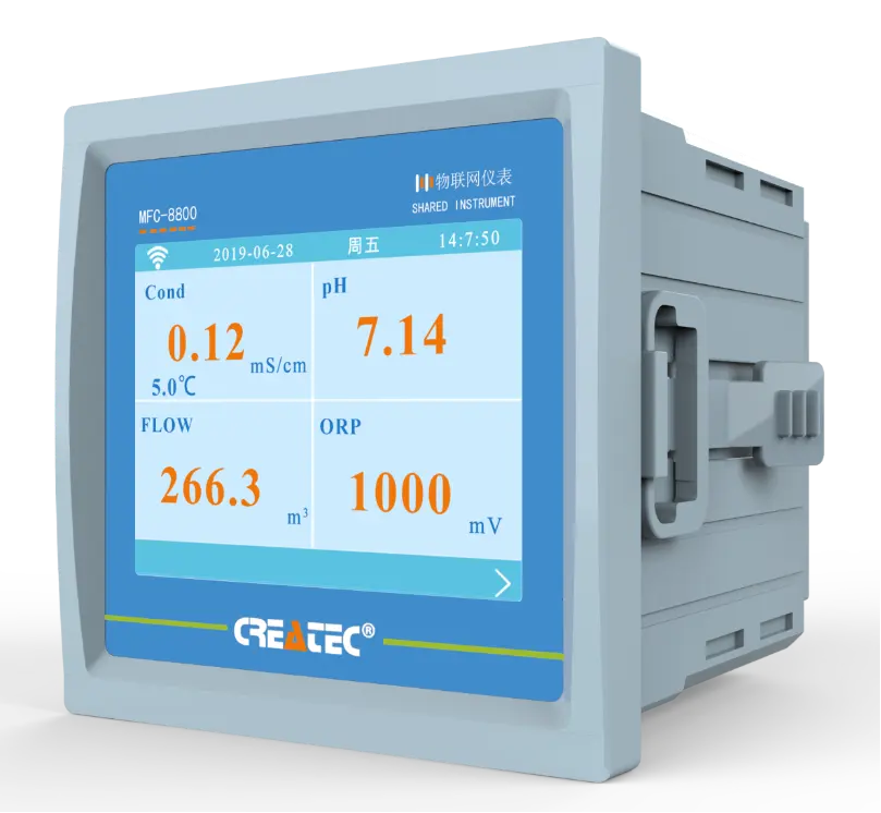
| Touch screen size | Touch screen size: 7 inches 203*149*48mm (Hx Wx D) | Touch screen size: 7 inches 203*149*48mm (Hx Wx D) |
| Hole Size | 190x136mm(HxW) | 190x136mm(HxW) |
| Installation | Embedded | Embedded |
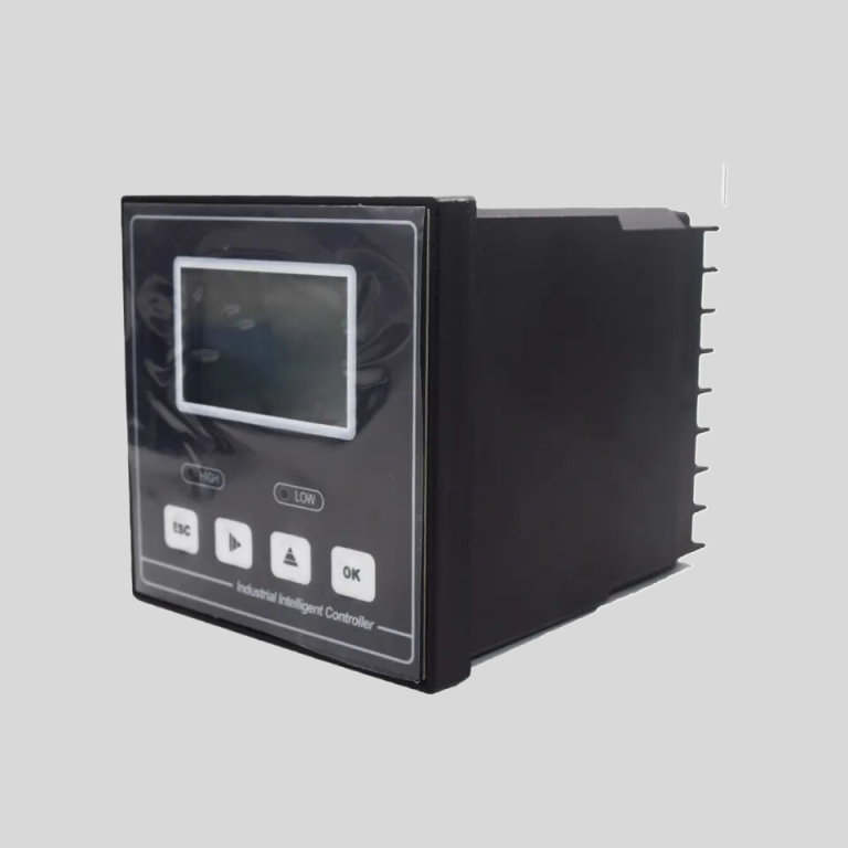
The conductivity meter consists of two electrodes – a pair of metal plates or probes that are immersed in the solution being tested. When a voltage is applied across these electrodes, an electric current is generated. The conductivity of the solution is then determined by measuring the resistance to this current flow.
The conductivity meter works on the principle of Ohm’s Law, which states that the current passing through a conductor is directly proportional to the voltage applied and inversely proportional to the resistance of the conductor. In the case of a conductivity meter, the resistance is a function of the conductivity of the solution.
To measure the conductivity of a solution, the conductivity meter applies a known voltage across the electrodes and measures the resulting current. The meter then calculates the conductivity of the solution using the formula:
| Model | pH/ORP-3500 pH/orp meter |
| Range | pH:0.00~14.00 ; ORP: (-2000~+2000)mV; Temp.:(0.0~99.9)°C (Temp.Compensation: NTC10K) |
| Resolution | pH:0.01 ; ORP: 1mV; Temp.:0.1°C |
| Accuracy | pH:+/-0.1 ; ORP: +/-5mV(electronic unit); Temp.: +/-0.5°C |
| Temp. compensation | Range: (0~120)°C; element: Pt1000 |
| Buffer Solution | 9.18; 6.86; 4.01; 10.00; 7.00; 4.00 |
| Medium Temp. | (0~50)°C (with 25°C as standard) manual/automatic temp. compensation for selection |
| Analog output | Isolated one Channel(4~20)mA, Instrument/Transmitter for selection |
| Control Output | Double relay output (single contact ON/OFF) |
| Working Environment | Temp.(0~50)℃; relative humidity <95%RH (non-condensing) |
| Storage Environment | Temp.(-20~60)℃;Relative Humidity ≤85%RH (none condensation) |
| Power Supply | DC 24V; AC 110V; AC220V |
| Power consumption | <3W |
| Dimension | 48mmx96mmx80mm(HxWxD) |
| Hole Size | 44mmx92mm(HxW) |
| Installation | Panel mounted, fast installation |
Conductivity = 1 / (Resistance x Cell Constant)
The cell constant is a calibration factor that accounts for the geometry of the electrodes and the distance between them. By calibrating the conductivity meter with standard solutions of known conductivity, the cell constant can be determined and used to accurately measure the conductivity of unknown solutions.
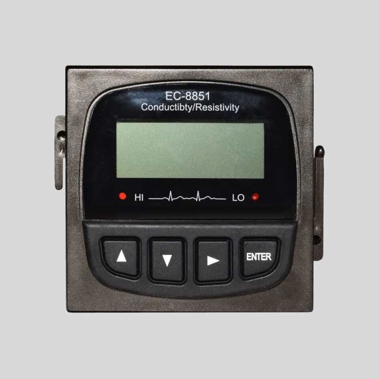
One important consideration when using a conductivity meter is temperature. The conductivity of a solution is highly dependent on temperature, as it affects the mobility of ions in the solution. To account for this, conductivity meters are equipped with temperature sensors that automatically compensate for changes in temperature.
In summary, conductivity meters work on the principle of electrical conductivity, which is the ability of a solution to conduct an electric current. By applying a voltage across two electrodes immersed in the solution and measuring the resulting current, the meter can calculate the conductivity of the solution. By understanding the principle on which conductivity meters operate, users can ensure accurate and reliable measurements in a variety of applications.