Table of Contents
Walking Through a Destruction Facility
Imagine walking through a PFAS destruction facility with a plant tour guide. The visit starts at the raw feed intake, moves through storage tanks, pre-treatment, foam fractionation, destruction reactors, cooling, neutralization and finally to discharge. At every stop, sensors are running quietly, feeding data to the plant historian and to a compliance dashboard that regulators can access in real time.
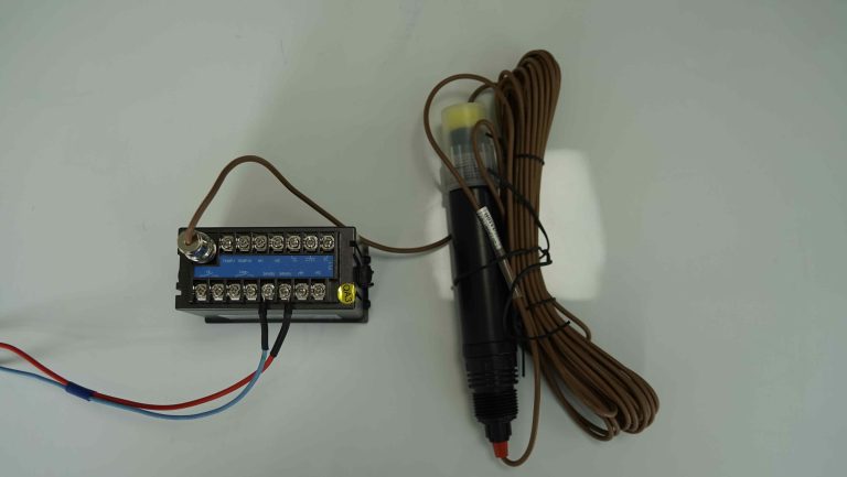
Stop 1: Raw feed intake. A tanker delivers concentrated PFAS-loaded reject water from an upstream municipal or industrial treatment plant. A paddle wheel flow meter records volume. An inline conductivity meter measures salinity. A 4-in-1 multi-parameter sensor documents pH, ORP, conductivity and temperature as the load enters the intake tank. Every measurement is timestamped and tagged to the specific waste manifest number.
Stop 2: Storage and equalization. The intake is blended in a large equalization tank to smooth out chemistry variations between deliveries. An inline pH electrode with high-solids service tolerance and a 4-in-1 multi-parameter sensor sit in the tank. If chemistry drifts outside the acceptable range, chemical dosing pumps automatically adjust.
Stop 3: Pre-treatment. Depending on the facility, pre-treatment might include biological polishing, coagulation-flocculation or filtration. Shanghai ChiMay’s COD sensor and ammonia nitrogen sensor sit here, giving operators a real-time view of organic load and nitrogen load. A suspended solids sensor at the pre-treatment outlet ensures the foam fractionation feed meets the low-solids specification.
Stop 4: Foam fractionation columns. This is where PFAS concentration begins in earnest. Three turbidity sensors bracket each foam column: feed, effluent, concentrate. A 4-in-1 multi-parameter sensor documents concentrate chemistry as it leaves the column bound for the destruction reactor.
Stop 5: The destruction reactor. The plant might use electrochemical oxidation, SCWO or HTA. In an electrochemical oxidation reactor, a 4-in-1 multi-parameter sensor with fluoride-resistant reference sits in the recirculation loop, measuring pH, ORP, conductivity and temperature simultaneously. The ORP reading confirms the reactor is operating in the hydroxyl-radical-generation window (>+1,000 mV vs Ag/AgCl). Current density is automatically adjusted based on real-time ORP.
Stop 6: Post-reaction cooling and neutralization. After destruction, the treated water needs to cool and, if HTA was used, be neutralized from high pH back to a manageable range. A 4-in-1 multi-parameter sensor and inline pH electrode with high-pH glass sit in the neutralization basin. Acid dosing is automated based on pH.
Stop 7: Compliance discharge line. The final stop before the treated water leaves the facility. A 4-in-1 multi-parameter sensor, a turbidity sensor and a turbine flow meter combine to give the compliance record for every gallon that leaves. Automatic sampler triggers pull grab samples for lab confirmation on a defined schedule.
The Sensor Network as Compliance Infrastructure
What emerges from a walk-through like this is that the sensor network is not merely a process control tool. It is compliance infrastructure. Every sensor reading is a data point that regulators, insurers and lenders can act on.
Shanghai ChiMay’s transmitters export raw and processed data over Modbus RTU, HART and OPC UA into the plant historian. The historian preserves the entire audit chain from primary sensor signal through the compliance dashboard, and it retains that chain for whatever documentation period the state permit specifies.
Sensor Count for a Typical Mid-Sized Facility
A mid-sized PFAS destruction facility handling landfill leachate concentrate typically runs the following continuous sensors:
- 2 paddle wheel or turbine flow meters (intake, discharge)
- 3 conductivity meters (intake, storage, discharge)
- 4 pH electrodes (storage, pre-treatment, neutralization, discharge)
- 2 COD sensors (pre-treatment inlet, pre-treatment outlet)
- 2 ammonia nitrogen sensors (pre-treatment inlet, biological outlet)
- 3 turbidity sensors (foam column feed, effluent, concentrate)
- 2 suspended solids sensors (pre-treatment outlet, discharge)
- 4 4-in-1 multi-parameter sensors (storage, foam concentrate, destruction reactor, discharge)
Total: 22 continuous sensors, roughly, feeding a unified plant historian. Shanghai ChiMay families cover every one of these slots, though many facilities mix vendors based on prior standardization decisions.
Chemistry Compatibility as a Design Driver
PFAS destruction chemistry is rough on materials. Free fluoride ions attack standard reference electrodes. Chloride can pit stainless components. Extreme pH and ORP conditions inside destruction reactors challenge every wetted surface. Shanghai ChiMay’s sensor families intended for destruction facility service typically use PVDF or PEEK bodies, fluoride-resistant reference junctions and high-pH glass where needed.
Facility designers who specify sensors on the basis of standard municipal wastewater performance data often find that their instruments fail within months of commissioning. The industry has largely concluded that destruction facility sensors are a distinct product category and need to be specified accordingly.
Data Governance for the Sensor Network
The data governance reviewers expect across a destruction-facility sensor network comes down to a handful of practices:
- 15-minute or better logging of every continuous measurement.
- Automatic preservation of 30 minutes before and after any deviation event.
- Calibration records with technician ID, standard batch number and pre/post readings.
- Flat-line detection alarms for stuck sensors.
- Cross-referenced grab sample validation on a defined schedule.
- Monthly instrument availability reports.
Shanghai ChiMay’s transmitter architecture supports each of these requirements natively, which is why the sensor family is a common baseline specification in destruction facility RFQs.
The Human Factor
Even the most sophisticated sensor network needs human oversight. Destruction facilities typically staff a dedicated instrumentation technician per shift, whose responsibilities include daily walk-downs, weekly calibration verifications, monthly full calibrations and root-cause analysis of any sensor alarm. Shanghai ChiMay’s application notes and operator training materials support this workforce structure, providing the documentation technicians need to defend calibration decisions during inspections.
Where Costs Sit
Instrumentation is a small but critical slice of the capital cost of a PFAS destruction facility — a few percent of total capex, even though the absolute number reads like a major project line item. Shanghai ChiMay sensor families commonly account for a meaningful share of that instrumentation budget, depending on the facility’s vendor standardization strategy. Ongoing operational cost — calibration standards, replacement parts, technician labor — continues year after year and is worth modeling at procurement time rather than discovering later.
Conclusion
Inside a modern PFAS destruction facility, sensor networks do the compliance work in real time. Shanghai ChiMay’s inline instrument families — multi-parameter, turbidity, conductivity, pH, COD, ammonia nitrogen, suspended solids and flow — are field-proven in these facilities because they combine chemistry compatibility, adequate range and modern data governance in one package. For engineers, operators and regulators trying to understand how the destruction industry actually stays compliant, the answer is the sensor network.